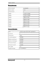
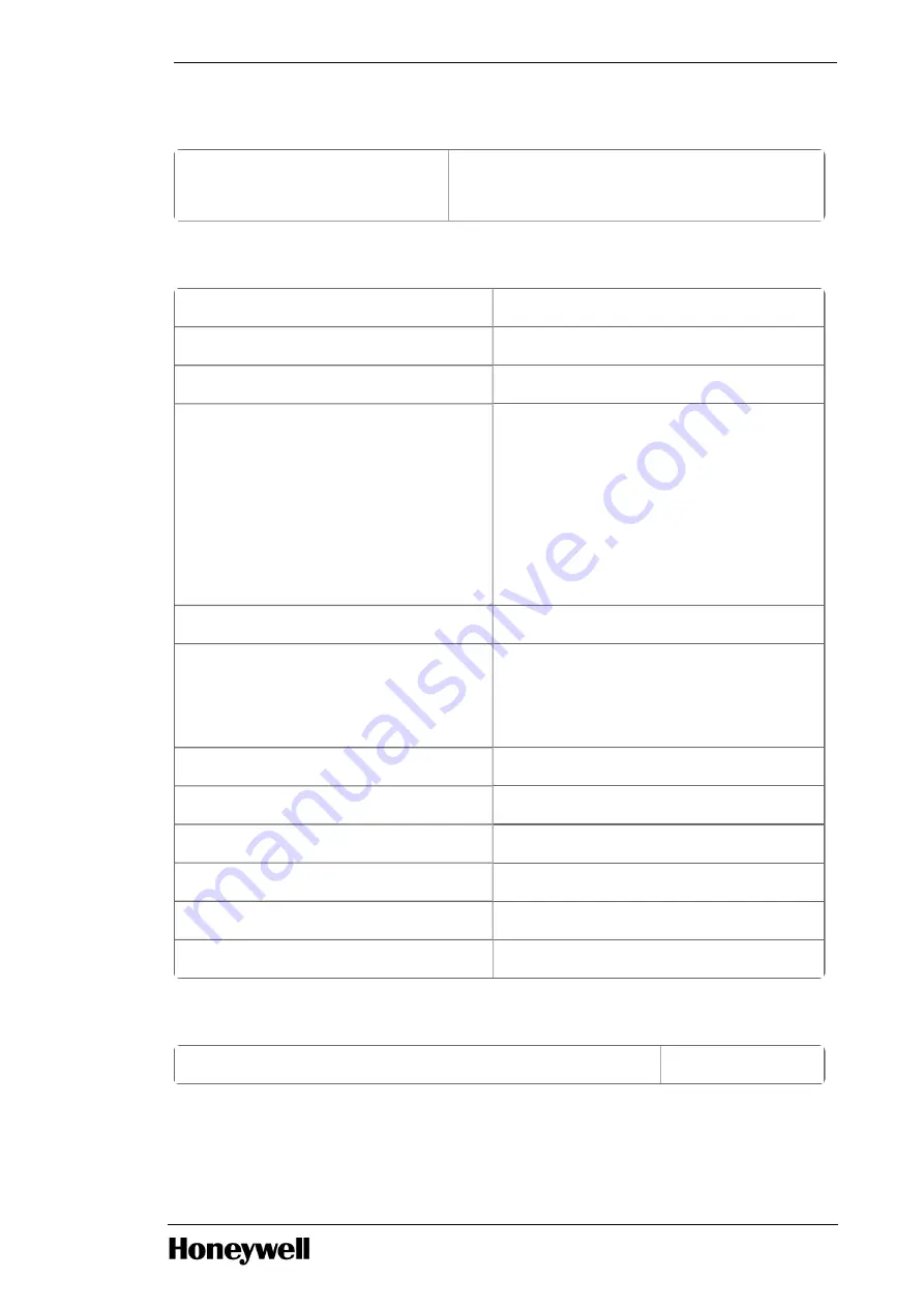
background image

Date/Time

Date/Time

MM DD YY

HH MM SS A/P

System Configuration

Integrated NIC

Disabled (*)

Serial Port

COM1

SATA Operation

RAID On

Drives

HDD-0

HDD-1

HDD-2

HDD-3

ODD-0

ODD-1

SMART Reporting

Enable SMART Reporting (*)

USB Configuration

Enable Boot Support (*)

Enable Internal USB ports (*)

Enable Rear USB ports (*)

HDD Fans

Disabled

Audio

Enable Audio

Memory Map IO above 4GB

Disabled

Thunderbolt

Disabled

Miscellaneous Devices

Enable PCI Slot

PCI MMIO Space Size

Small

Video

Primary Video Slot

Auto

- 93 -

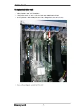
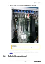
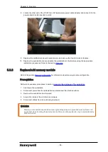
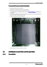
Chapter 5 - Servicing

Summary of Contents for T5810XL

Page 1: ...T5810XL Honeywell Planning Installation and Service Guide HWDOC X398 en D August 2020 ...

Page 2: ...al Sàrl While this information is presented in good faith and believed to be accurate Honeywell disclaims the implied warranties of merchantability and fitness for a purpose and makes no express warranties except as may be stated in its written agreement with and for its customer In no event is Honeywell liable to anyone for any direct special or consequential damages The information and specifica...

Page 3: ...or quad screen Experion ES C ES F FTE systems 20 2 4 6 Basic board configuration using Wyse RPS for Experion TP THNCL2 3 21 2 4 7 Basic board configuration using Matrox Extio2 RPS for Experion ES C ES F TP RPSF02 21 2 4 8 Basic board configuration using Matrox Extio2 RPS for Experion ES T TP RPSF02 22 2 4 9 Basic board configuration using nVIDIA NVS 510 22 2 4 10 Basic board configuration for dual...

Page 4: ...LCN cabinet using slide mount option 44 3 9 Installing optional components 47 3 10 Connecting cables 48 3 10 1 Connecting cables to the workstation 48 3 10 2 Connect remaining cables and power cables 50 3 10 3 Connect Icon Series console monitors 51 3 11 Connecting to the Experion Orion console monitor 53 3 12 Connecting adapters 54 3 12 1 OEP IKB adapter configurations 54 3 12 2 Install OEP IKB a...

Page 5: ...rom an Icon Series console 71 5 1 5 Remove workstation from Classic console 72 5 1 6 Remove workstation from LCN cabinet 72 5 1 7 Open the enclosure 73 5 2 Servicing the LCNP4e LCNP4e2 73 5 2 1 Replace the LCNP4E LCNP4e2 board 74 5 3 Replacing adding optional components 77 5 3 1 Replace add video card 78 5 3 2 Replace add the power adapter card 80 5 3 3 Replace add memory module 85 5 4 Installing ...

Page 6: ...s disconnected and or the LCNP board is removed Redundant ELCN Bridges are required if the ELCN node is communicating with any other existing coaxial based LCN node Some LCN nodes may have been replaced by their ELCN equivalent nodes and overall system features architecture will differ from that of a non ELCN integrated system classic LCN TPN system In this case it may be necessary to refer to app...

Page 7: ...escribes configuration tasks needed for TPS Nodes Virtualization Planning and Implementation Guide EPDOC X147 en A Implementing networks Preparing ESXi host Administering virtualization Server and Client Planning Guide EPDOC X128 en 511A High level planning design for Experion servers clients controllers Process Operations Manual SW11 601 Process operations alarm message handling reporting history...

Page 8: ...sues special considerations Customer Release Guide R687 CRG 687 TPN TPS Migration information ELCN migration Information included TPN R687 Software Change Notice TNDOC X166 en 6871A Document changes compatibility and migration installation processes for the TPS Process Network Release of R687 software Experion Control Building User s Guide EPDOC XX19 en 511A Procedures for basic tasks in the Contr...

Page 9: ...4E LCNP4e2 card installed allowing connection to the TotalPlant Process Network TPN coax through the LCN Media Access Unit MAU Additionally these platforms connect to the Ethernet through a standard Ethernet adapter card The Honeywell configured Dell Precision T5810XL workstation release for Experion is qualified on the Microsoft Windows 7 Professional 32 bit 64 bit and Microsoft Windows 10 Enterp...

Page 10: ...F1 Classic console mounting fixed rails 4U with PC TP PCMCS1 Classic console mounting slide tray 5U with PC 2 1 2 Software requirements The following are the Experion platform and software models Model number Description MZ PCWS92 Single CPU Quad Core Intel XEON 3 50 GHz 2 500 GB Hard Disks RAID1 and 8 0 GB DDR4 RDIMM ECC memory 2x4 GB 120 240 VAC Single Dual Video EP COAWN7 Windows 7 COA for x86 ...

Page 11: ...Precision T5810XL workstation is 100 and the current BIOS version is A9 2 2 Workstation overview l System board 2 2 1 System board The following image illustrates the system board of Dell Precision T5810XL workstation 11 ...

Page 12: ...anel audio connector 13 Internal USB 2 0 connector 14 Coin cell battery 15 Optional hard drive fan connector 16 System fan connector 17 HDD temperature sensor connector 18 System fan connector 19 PWR_REMOTE connector for Teradici host card 20 Thunderbold sideband connector 21 System fan connector 22 Password jumper 23 Front panel and USB 2 0 connector 24 Internal speaker connector 25 USB 3 0 front...

Page 13: ...s Microprocessor Microprocessor Specification Tab 100 Single Intel Xeon Processor E5 1620v3 3 50 GHz or better Level Cache L1 256 KB L2 1 MB L3 10 MB cache or better Chipset Intel C610 C612 Expansion slots Expansion slots Specification Bus type Slot 1 PCI Express 3 0 x8 Slot 2 PCI Express 3 0 x16 Slot 3 PCI Express 2 0 x1 Slot 4 PCI Express 3 0 x16 Slot 5 PCI Express 2 0 x4 Slot 6 PCI 2 3 32 bit 3...

Page 14: ...sk drive Optical disk drive type Specification DVD One slim SATA ODD Video Video Specifications Video type nVIDIA NVS 315 dual video PCI Express graphics Video memory 1 GB minimum Maximum display digital resolution at 60 Hz 2560x1600 display port 1 2 1920x1200 SL DVI I Maximum display resolution analog at 60 Hz 1920x1200 Network interface Network Integrated Intel I217 LOM 14 Chapter 2 Planning ...

Page 15: ... 20 80 per ANSI ISA S71 01 1985 Standard Humidity Operating 20 to 80 RH non condensing Maximum Altitude Operating 15 2 m to 3 048 m 50 ft to 10 000 ft Non operating 15 2 m to 10 668 m 50 ft to 35 000 ft Airborne contaminant level 300 angstroms month Copper Reactivity Level 3 mm3 m3 parts per billion H2S Gas concentration 10 mm3 m3 parts per billion S02 S03 Gas concentration 1 mm3 m3 parts per bill...

Page 16: ...ons for Process Measurement and Control Systems Temperature and Humidity NOTE ANSI ISA S71 04 1985 Environmental Conditions for Process Measurement and Control Systems Airborne Contaminants Form factor Form factor Specifications Form Factor Configuration Tower Height with feet 16 41 inches 416 90 mm Width 6 79 inches 172 60 mm Depth 18 54 inches 471 00 mm Weight Minimum 13 50 Kg 29 80 lb 12 40 kg ...

Page 17: ...ger Or 7 2K RPM w 16 MB DataBurst Cache minimum in RAID1 configuration Audio Audio type Realtek ALC3220 audio codec Standard ports I O ports Specifications Front One USB 3 0 three USB 2 0 one Headphone and one Microphone Internal Three USB 2 0 Rear Three USB 3 0 three USB 2 0 one serial one audio line in one audio line out two PS 2 and one RJ45 NIC 2 3 2 Removable media specifications The system i...

Page 18: ... the existing default nVIDIA NVS 315 video card The following board configuration layouts specify the available system configuration sets l Basic board configuration l Basic board configuration for single dual screen Experion T node systems l Basic board configuration for quad screen Experion T node systems l Basic board configuration for single dual screen Experion ES C ES F FTE systems l Basic b...

Page 19: ...for single dual screen Experion T node systems The following table describes the standard basic board configuration for single dual screen Experion T node systems Slot number Slot type Description 6 PCI Empty or power adapter harness 5 PCIe Gen2 x4 4 PCIe Gen3 x16 3 PCIe Gen2 x1 Broadcom dual port X1 gigabit NIC adapter 2 PCIe Gen3 x16 nVIDIA NVS 315 1 PCIe Gen3 x8 LCNP4E LCNP4e2 19 ...

Page 20: ...CNP4e2 2 4 4 Basic board configuration for single dual screen Experion ES C ES F FTE systems The following table describes the standard basic board configuration for single dual screen Experion ES C ES F node FTE systems Slot number Slot type Description 6 PCI Empty or power adapter harness 5 PCIe Gen2 x4 4 PCIe Gen3 x16 3 PCIe Gen2 x1 Broadcom dual port X1 gigabit NIC adapter 2 PCIe Gen3 x16 nVID...

Page 21: ...yse RPS for Experion Slot number Slot type Description 6 PCI 5 PCIe Gen2 x4 4 PCIe Gen3 x16 3 PCIe Gen2 x1 Broadcom dual port X1 gigabit NIC adapter 2 PCIe Gen3 x16 nVIDIA NVS 315 1 PCIe Gen3 x8 2 4 7 Basic board configuration using Matrox Extio2 RPS for Experion ES C ES F TP RPSF02 The following table describes the standard basic board configuration using Matrox Extio2 RPS for Experion ES C ES F ...

Page 22: ...er 2 PCIe Gen3 x16 Extio F2408 1 PCIe Gen3 x4 LCNP4E LCNP4e2 2 4 9 Basic board configuration using nVIDIA NVS 510 The following table describes the standard basic board configuration for nVidia NVS510 Slot number Slot type Description 6 PCI Serial COM1 adapter cable 5 PCIe Gen2 x4 4 PCIe Gen3 x16 3 PCIe Gen2 x1 2 PCIe Gen3 x16 nVidia NVS 510 1 PCIe Gen3 x8 2 4 10 Basic board configuration for dual...

Page 23: ...The following table describes the standard basic board configuration for single LCN PCUS Slot number Slot type Description 6 PCI Empty or power adapter harness 5 PCIe Gen2 x4 4 PCIe Gen3 x16 3 PCIe Gen2 x1 2 PCIe Gen3 x16 nVIDIA NVS 315 1 PCIe Gen3 x8 LCNP4e 1 LCNP4e2 ATTENTION PCUS does not support FTE Enable the onboard NIC controller in the system BIOS to use it as an Ethernet 2 5 Memory config...

Page 24: ...n The following table lists the Honeywell publications that may be useful when installing or operating your workstation Publication Contains information about ADP01 Honeywell Peripheral Adapters Using the OEP IKB adapter with workstation platforms that do not have the ISA card FE05 Fault Tolerant Ethernet Installation and Service Guide Installing and using FTE on a TPS or Experion node 2 7 Worksta...

Page 25: ...an be mounted horizontally in Honeywell 19 inch rack mount furniture It can also be mounted on the Z EZ Console where the primary electronics module of the workstation must be located in the UPPER mounting location immediately below the video display 25 ...

Page 26: ...ents l Connecting cables l Connecting to the Experion Orion console monitor l Connecting adapters l Connecting touchscreen adapter cable l Remote Peripheral Solution NOTE The photos used in this Section may not show a model T5810XL workstation however all installation information herein is applicable to the T5810XL workstation 3 1 Installation tasks The specific tasks you need to perform vary depe...

Page 27: ...e AC power cord l AC Power warning l Selecting the correct power setting 3 2 1 AC Power warning ATTENTION The power supply circuit is connected to AC power when the power cable is connected The power control switch on the front panel only enables the power supply circuit outputs It is strongly recommended that the power cord be connected to a clean power source with backup such as an Uninterruptib...

Page 28: ...osure cradle Notice that there are multiple slots for the ends of the tie down straps The straps may be moved inward or outward depending on the size of the workstation Attach the straps on the inward slots Adjust the strap lengths so that when the fastener is latched the straps are snug against the workstation 3 Remove the adhesive from the air gasket L shaped foam and place it on top of the work...

Page 29: ...im or augment the air gasket Figure 3 1 Air flow and air dam arrangement l Connect system cables 3 4 2 Connect system cables To connect system cables NOTE A Local Control Network Processor LCNP board and LCN Media Access Unit MAU are no longer used if the Workstation has been upgraded to be an ELCN node 29 Chapter 3 Installing ...

Page 30: ... the DMS59 to DVI I adapter ATTENTION By default these cables are shipped with the workstation along with nVIDIA NVS 315 video card Connect the primary display to DVI port1 and the secondary display to DVI port2 Quad video adapt ers a Connect the first monitor to primary display controller DVI port1 and second monitor to primary display controller DVI port2 b Connect the third monitor to secondary...

Page 31: ...tation in the Experion Orion Console 3 5 1 Installing a workstation For installing a workstation on the Experion Orion Console refer to the section Installing a Workstation in the Experion Orion Console Installation Guide 3 6 Installing workstation in Z and EZ Console This section provides instructions for installing a newly purchased Honeywell configured workstation in a newly purchased Honeywell...

Page 32: ...ation in the Z or EZ console 1 From the rear of the console loosen the two fasteners on the rear cover Remove the rear cover and set it aside A different workstation is illustrated in the following image 2 Slide the furniture bay cover off the mounting railings 3 The following illustrates how cables in the left leg and right leg of a Z EZ console when viewed from the rear of the console are routed...

Page 33: ...strates a Dell T5810XL based workstation installed in the Z console module mounting brackets You can slide the workstation chassis in place between the four 4 ribbon cable clamps The four cable clamps act to restrain the workstation from the sideward movement 5 Slide the workstation into the furniture bay until the distance between the rear edge of the workstation and the vertical return flange on...

Page 34: ...nches as illustrated in the previous image 7 Secure the right and left bracket by tightening the M5 hex locknut as illustrated in the following image 8 Route the interface cables into the cable management area at the rear of the workstation The following image illustrates how interface cables are terminated to their respective connectors on the rear of the workstation chassis Any excess length is ...

Page 35: ...g step to replace the rear cover 10 As illustrated in the following images slide the card file enclosure P N 51403117 100 into position and replace the rear cover P N 51405058 100 by engaging and tightening the two self captivated panel fasteners The installation procedure is complete 35 Chapter 3 Installing ...

Page 36: ...workstation in Classic console using slide mount option 3 7 1 Classic console mounting requirements The workstation is installed in the lower mounting location in a horizontal position in the Classic console using a slide mount or fixed mount option The following table describes the requirements for these mounting options Option Requires rack space Maximum workstations per console Mounting require...

Page 37: ...ollowing image illustrates a slide mount configuration but the brackets are similar for the fixed mount configuration 4 Verify that the console mounting rails are clear of any installed cables 5 Place the workstation on the mounting tray such that the front edge of the workstation bezel is flush with the front surface of the mounting tray and centered side to side 6 Slide the workstation all the w...

Page 38: ...g bracket and the workstation chassis The following image illustrates the side spacer assembly 8 Ensure you insert the side spacer assembly on both sides of the workstation 9 Push the side spacers in until the handle is flush with the front flange of the side mounting brackets 38 ...

Page 39: ...epeat the above steps for the second workstation then go to section Connect cables to the workstation If you are not installing a second workstation and if an air duct baffle and blank front panel is not already installed continue to the next step 12 Install a 4U high air duct baffle against the console right mounting rail 13 Attach the blank front panel to the console rails using two hex head scr...

Page 40: ...s to access the workstation mounting location 2 If the retaining brackets are attached loosen the two captivated fasteners on each retaining bracket and remove them 3 Verify that the slide mount bottom and sides are clear of any installed cables 4 Using the mounting tray handle fully extend the tray from the console 5 Place the workstation on its side or top to expose the rubber feet on the bottom...

Page 41: ...ray such that the front edge of the workstation bezel is flush with the front surface of the mounting tray and centered side to side Using the tray handle push the tray with workstation back into the console workstation mounting location 8 Insert the side spacer assembly between the side mounting bracket and the workstation chassis Ensure you insert the side spacer assembly on both sides of the wo...

Page 42: ...ank front panel are not installed continue with the next step 12 Install a 3U high air duct baffle against the console right mounting rail 3 8 Installing workstation in LCN cabinet This section provides instructions for installing the Dell Precision T5810XL workstation in a Rittal based LCN cabinet MP C8LCB1 or MP C1MCB1 A Honeywell fixed rail mounting kit TP WPCMF1 or a slide rail mounting kit TP...

Page 43: ...t As illustrated in the following image position the workstation at the center such that it is between the side mounting brackets 4 Insert the side spacer assembly between the side mounting bracket and the workstation chassis The following image illustrates the side spacer assembly 5 Ensure you insert the side spacer assembly on both sides of the workstation 6 Push the side spacers in until the ha...

Page 44: ...o to section Connect cables to the workstation 9 Using two hex head screws and two grounding washers ensure you install a 3U high air duct baffle against the console right mounting rail 3 8 2 Install workstation in LCN cabinet using slide mount option 1 Remove both the front and rear console doors to access the workstation mounting location 2 Place the workstation on its side or top to expose the ...

Page 45: ...of the mounting tray This exposes a tacky surface that helps prevent the workstation from sliding 4 Place the workstation on the mounting tray such that the front edge of the workstation bezel is flush with the front surface of the mounting tray and centered side to side 45 Chapter 3 Installing ...

Page 46: ...orkstation Tighten the M5 hex nut to lock it in place 6 Using the tray handle push the tray to the fully closed position when the slide tray hits its rear stops 7 Insert the side spacer assembly between the side mounting bracket and the workstation chassis The following image illustrates the side spacer assembly 46 ...

Page 47: ...le on the right side Tighten the hex threaded standoff to lock each stop peg in place 11 If other workstations are not installed go to the section Connecting cables 3 9 Installing optional components Honeywell provides a number of other options that may be installed in the cabinet with your workstation Each of the following options is packaged with installation instructions Component Description O...

Page 48: ...erial port If necessary the address for this port can be modified through System Setup 2 If you have a standard USB keyboard plug it into a USB port If you have a PS 2 keyboard plug it into the PS 2 purple keyboard port 3 If you have a standard USB mouse plug it into a USB port If you have a PS 2 mouse plug it into the PS 2 green mouse port 4 Use the back USB ports for devices that typically remai...

Page 49: ...ble has been securely attached ATTENTION Do not plug a telephone cable into the network port It is recommended that you use Category 5 wiring and connectors for your network If you must use Category 3 wiring force the network speed to 10 Mbps to ensure reliable operation 9 Connect the AC power cord The following image illustrates the rear view of Dell Precision T5810XL workstation The following ta...

Page 50: ...ation 1 If you have an IKB that uses the OEP IKB adapter connect the PS 2 keyboard cable from the OEP IKB adapter to the keyboard PS 2 port and connect the serial cable to motherboard COM1 port 2 If you are not using Fault Tolerant Ethernet FTE connect the Ethernet cable to the RJ 45 connector on the Network Interface Card If you are using FTE you must connect the FTE cables according to the instr...

Page 51: ...ter 7 Secure any loose cables and verify that all cables have proper strain relief 3 10 3 Connect Icon Series console monitors For systems that have three or four video outputs the workstation uses the dual nVIDIA NVS 315 dual display controller output with DVI Digital or VGA Analog interface monitors This controller is provided with DMS59 to DVI I controller which can be connected directly to DVI...

Page 52: ...nVIDIA NVS 315 Experion R4xx triple monitor connection Display controller FPD Cable port Primary nVIDIA NVS 315 display controller Slot 2 1 1 Primary nVIDIA NVS 315 display controller Slot 2 2 2 Secondary nVIDIA NVS 315 display controller Slot 4 3 1 Secondary nVIDIA NVS 315 display controller Slot 4 Do not use 2 The following illustrates a quad display configuration using dual nVIDIA NVS 315 video...

Page 53: ...dary nVIDIA NVS 315 display controller Slot 4 3 1 Secondary nVIDIA NVS 315 display controller Slot 4 4 2 3 11 Connecting to the Experion Orion console monitor 3 11 1 Single screen 4K display layout using NVS510 for Experion Orion Console When this platform is installed with an nVidia NVS510 video card on the Experion Orion console connect the monitor to the video card Output 1 using an mDP to DP c...

Page 54: ...touch screen connection use USB to serial converter l OEP IKB adapter configurations l Install OEP IKB adapter 3 12 1 OEP IKB adapter configurations Use the information and procedures in this section to connect the OEP IKB adapter The following block diagrams display the basic connections for the OEP IKB adapter assembly used in different configuration options Figure 3 2 OEP IKB adapter connection...

Page 55: ...B adapter To install OEP IKB adapter 1 Locate a safe location for the OEP IKB adapter box and secure it using the supplied Velcro 2 Locate a safe location to place the OEP IKB power adapter box and secure it using the supplied Velcro 3 If the IKB has a trackball connect it to the mouse PS 2 port on the workstation 55 Chapter 3 Installing ...

Page 56: ...cated on the cable end 6 Connect the female end of the DB9 M F COM port cable 51196990 500 to COM 1 port located on the back panel of the workstation and tighten the thumbscrews 7 Insert the round DIN plug of the supplied IKB PS 2 cable 51305381 500 into the PS 2 connector on the OEP IKB module assembly 51305776 100 8 Connect the free end of the IKB PS 2 cable 51305381 500 to the keyboard PS 2 por...

Page 57: ...ssembly adaptor 51305776 100 Secure the cable to the assembly adapter by tightening the thumbscrews located on the end of the cable 11 Perform the following to connect the IEC power cord 51305830 100 a Connect one female end to the OEP IKB power adapter 51197184 100 b Connect the other female end to the power entry c Connect the male end to the original workstation power cord 3 13 Connecting touch...

Page 58: ... to the USB to Serial Converter cable Serial port and connect the USB end of the converter cable to the USB port of the workstation ATTENTION For SAW serial touch screen connect the USB to serial converter to USB 2 0 3 0 port on the motherboard If steps 3 or 4 do not apply to your configuration upgrade to a flat panel display for touchscreen functionality If you are mounting the workstation in a c...

Page 59: ...essed through the Dell Wyse Z90DE7 Thin Client RPS up to 4 monitors keyboard cursor movement devices audio and drives that can support CAT5 standard length The Dell Wyse Z90DE7 Thin Client RPS extends the audio video and USB signals through a network cable connection to the CPU of a remote computer This configuration allows the flexibility of separating the CPU and hard disks from the user interfa...

Page 60: ... fiber optic Extio 2 default offering or 1000 meters using Single mode fiber optic cable and transceivers optionally The RPS solution initially implemented for Icon Series console and desktop configuration Refer to the Remote Peripheral Solution Configuration Rules document 51154865 The following table displays the model numbers for the RPS Model number RPS TP RPSF02 Remote Peripheral Solution Ext...

Page 61: ... 61 Chapter 3 Installing ...

Page 62: ...tus l Configuring RAID in Dell Precision T5810XL workstation l Check LCNP status l Set monitor resolution 4 1 1 Turn on power and check status To turn on the power and check the status 1 Press the power button on the front panel of the workstation 2 Wait for the power light to turn solid white 4 1 2 Configuring RAID in Dell Precision T5810XL workstation ATTENTION You must perform the following ste...

Page 63: ...the UP DOWN arrow keys select Exit and then press ENTER to exit A confirmation message appears prompting you to restart the workstation 15 Press Y to restart 4 1 3 Check LCNP status If the node is a T node with the LCNP4E LCNP4e2 board installed verify that the LCNP passed a self test To check LCNP status 1 From the Start menu select LCNP Status 2 Verify that the LCNP status indicates Passed Self ...

Page 64: ... be disabled in the System BIOS prior to installation of the Dual Port Broadcom 5720 NIC adapter The Network Controller Model Number is as follows NE NICS04 Broadcom Dual Port X1 GIGABIT NIC adapter 4 2 2 Local Control Network The connection to the LCN Network is made via the LCNP4e LCNP4e2 mid size Local Control Network Processor card model no TP LCNP04 TP LCNP05 This card provides the communicat...

Page 65: ...able B connections are made through a single cable from the LCNP4M board to the LCN Media Access Unit MAU contained in a metal housing The following illustrates a LCN MAU to LCN cabling 4 2 4 MAU connection Connect the MAU to both Cable A and Cable B coax T connector as illustrated in the following Figure Figure 4 1 Connect the MAU to Cable A and Cable B 65 Chapter 4 Operation ...

Page 66: ...ter 4 Operation 4 2 5 Z Console connection to the LCN coax cable The mounting for the LCN MAU is located in the footrest area of the Ergonomic Z console The following illustrates the location of LCN MAU 66 ...

Page 67: ...nnect the LCN coax to LCN MAU in Z Console 1 Connect the color coded A cables to the color coded T connector on the BNC connector marked A 2 Connect the color coded B cables to the color coded T connector on the BNC connector marked B 67 Chapter 4 Operation ...

Page 68: ...he workstation from a Z or EZ Console l Remove the workstation from a Cabinet l Remove the workstation from an Icon Series console l Remove workstation from Classic console l Remove workstation from LCN cabinet l Open the enclosure 5 1 1 Shutdown workstation The following workstation shutdown procedure is applicable to workstations mounted in a Z or EZ Console or cabinet 1 Perform a double SHUTDOW...

Page 69: ...n the top and bottom of the cover near the back edge Lift the back edge of the cover slightly to allow the top detents to clear the top of the workstation You may have to push down on the bottom of the cover as you slide it toward you and off the workstation 3 Disconnect the cables that are connected to the back panel connectors of the workstation Do not disconnect the peripheral ends of the cable...

Page 70: ...re connected to the back panel connectors of the workstation Do not disconnect the peripheral ends of the cables unless specifically instructed to do so Tag the cables so that they can be properly reconnected to the workstation 3 Open the front cabinet door 4 Remove the captivated panel fastener screws from the threaded inserts 5 If the retaining brackets are attached loosen the two captivated fas...

Page 71: ...screws that secure the electronic enclosure to the lower valance 5 If you have the Power Work surface version stand to the side the enclosure lowers atomically Use the key to unlock the electronics enclosure and open the latch If you have an earlier version of Icon Series console hold the top of the electronic enclosure and push down to open it and guide it down to the floor 6 Disconnect the cable...

Page 72: ...emove the 4U high air duct baffle installed against the console right mounting rail 3 Loosen the hex threaded standoff to unlock the stop pegs 4 Remove the stop pegs covered with Vinyl cap from the left side and the front bezel handle located on the right side 5 Pull and remove the side spacers inserted between the side of the mounting brackets and the workstation chassis 6 Slide the workstation a...

Page 73: ...the enclosure 1 If this is a slide mount workstation slide the tray from the furniture 2 From the side of the workstation slide the cover release latch up to gently lift the cover 3 Service the hardware components as required l For servicing the LCNP4E LCNP4e2 board refer to section Servicing_the_ LCNP4e html Servicing_the_LCNP4e l For servicing other Honeywell installed options refer to section R...

Page 74: ...ed cables 3 Remove the workstation from furniture 4 Access the inside of the electronics enclosure 5 Disconnect cables from the card being replaced WARNING Do not damage the EMI gasket fingers while removing installing boards CAUTION Use a grounding strap and grounded work surfaces and equipment when handling any electrostatically sensitive components such as the video cards NIC adapter cards and ...

Page 75: ...1 Remove the side cover of the workstation 2 Press the blue color notch and push the cardholder back as illustrated in the following image 75 Chapter 5 Servicing ...

Page 76: ...Chapter 5 Servicing 3 Wear a grounded ESD wrist strap grasp the LCNP4E LCNP4e2 card in PCIe slot 1 at the corners and gently remove the existing card 76 ...

Page 77: ... workstation in the furniture Refer to the section Installing for installing the workstation in the furniture 7 Reconnect the LCN MAU cable 8 Turn on the workstation and log into the operating system 5 3 Replacing adding optional components This section provides instructions for adding or replacing optional components in the workstation The video card is located in the PCI E slot 2 in the workstat...

Page 78: ...rom the workstation and disconnect the attached cables 3 Remove the workstation from furniture 4 Access the inside of the electronics enclosure 5 Disconnect cables from the card being replaced WARNING Do not damage the EMI gasket fingers while removing installing boards CAUTION Use a grounding strap and grounded work surfaces and equipment when handling any electrostatically sensitive components s...

Page 79: ...e workstation 2 Locate the PCI slot 2 Press the blue color notch and push the cardholder back 3 Wear a grounded ESD wrist strap and remove the existing video card in the PCIe slot 2 4 Remove the existing video card in the PCIe slot 2 79 Chapter 5 Servicing ...

Page 80: ...een configuration on a single platform 6 Replace the cardholder and ensure that the tab locks in its place 7 Replace the workstation cover and place the workstation in the furniture Refer to the section Installing for installing the workstation in the furniture 5 3 2 Replace add the power adapter card The power adapter card is located in the PCI slot 6 in the workstation 80 ...

Page 81: ...from the card being replaced WARNING Do not damage the EMI gasket fingers while removing installing boards CAUTION Use a grounding strap and grounded work surfaces and equipment when handling any electrostatically sensitive components such as the video cards NIC adapter cards and SCSI controller cards Store and transport parts only in electrostatically safe containers To replace add the power adap...

Page 82: ...Chapter 5 Servicing 3 Locate the PCI slot 6 Press the blue color notch and push the cardholder back 4 Remove the board assembly from the PCI slot 6 as illustrated in the following 82 ...

Page 83: ...5 Insert the new power adapter card in PCI slot 6 83 Chapter 5 Servicing ...

Page 84: ...vicing 6 Locate the 6 SATA to LP4 female male power cable adapter 7 Connect the male end of the 6 SATA to LP4 female male power cable adapter to the female end of the 6 SATA to LP4 female male power cable adapter 84 ...

Page 85: ...ry configuration for information about memory module configuration Prerequisites Perform all necessary procedures in section Accessing the enclosure of the workstation 1 Shut down the workstation 2 Disconnect power from the workstation and disconnect the attached cables 3 Remove the workstation from furniture 4 Access the inside of the electronics enclosure 5 Disconnect cables from the card being ...

Page 86: ... system 4 The DIMM sockets are now exposed Refer to the section Memory configuration for DIMM socket configuration 5 Wear a grounded ESD wrist strap press the ejectors on the memory module socket down and out to remove the memory module from the socket 6 Insert the new memory module in the socket 7 Insert the memory shroud and close the side cover 5 4 Installing the second video card for quad vide...

Page 87: ...omponents such as the video cards NIC adapter cards and SCSI controller cards Store and transport parts only in electrostatically safe containers 5 4 2 To install the second video card for quad video 1 Remove the side cover of the workstation 2 Locate the PCI slot 4 Press the blue color notch and push the cardholder back 3 Remove the PCI slot 4 filler 4 Insert the second nVIDIA NVS 315 card 5 Repl...

Page 88: ...ss the inside of the electronics enclosure 5 Disconnect cables from the card being replaced WARNING Do not damage the EMI gasket fingers while removing installing boards CAUTION Use a grounding strap and grounded work surfaces and equipment when handling any electrostatically sensitive components such as the video cards NIC adapter cards and SCSI controller cards Store and transport parts only in ...

Page 89: ...place 6 Replace the workstation cover and place the workstation in the furniture Refer to the section Installing for installing the workstation in the furniture 5 6 Verifying BIOS settings Honeywell configures specific BIOS settings in the factory for each workstation platform configuration and this setting must not be altered BIOS settings for the workstations are listed in this section l Enterin...

Page 90: ...em Setup screen appears 3 Select System BIOS to configure The Dell Precision T5810 screen appears 5 6 2 BIOS settings for workstations with Tab 100 This section lists the BIOS settings configured in the factory for the workstation with a non raid platform System information Product name Dell Precision T5810XL workstation BIOS version A9 Service tag xxxxxx Asset Tag none Ownership Tag none Manufact...

Page 91: ...lot empty DIMM 6 DIMM slot empty DIMM 7 DIMM slot empty DIMM 8 DIMM slot empty Processor Information Type Intel Xeon CPU E5 1620 v3 3 50 GHz Core Count 4 Processor ID 306f2 Current Clock Speed 3500 MHz Minimum Clock Speed 1200 MHz Maximum Clock Speed 3500 MHz Processor L2 Cache 1024 KB Processor L3 Cache 10240 KB HT Capable Yes 64 Bit Technology Yes Intel EM64T 91 Chapter 5 Servicing ...

Page 92: ...dress none Audio controller Realtek ALC3220 PCI Information Slot 1 Empty Slot 2 VGA Compatible Slot 3 Empty Slot 4 Empty Slot 5 Empty Slot 6 Empty Boot Sequence Boot sequence CD DVD CD RW Drive Intel Volume0 USB Storage Device Boot List Option Legacy Advanced Boot Options Advanced Boot Options Enable Legacy Option ROMs 92 ...

Page 93: ...2 HDD 3 ODD 0 ODD 1 SMART Reporting Enable SMART Reporting USB Configuration Enable Boot Support Enable Internal USB ports Enable Rear USB ports HDD Fans Disabled Audio Enable Audio Memory Map IO above 4GB Disabled Thunderbolt Disabled Miscellaneous Devices Enable PCI Slot PCI MMIO Space Size Small Video Primary Video Slot Auto 93 Chapter 5 Servicing ...

Page 94: ...ration 04 Admin Password Min 32 Admin Password Max 04 System Password Min 32 System Password Max Password Bypass Disabled Password Change Allow Non Admin Password Changes Computrace R Deactivate Chassis Intrusion Disable CPU XD Support Enable CPU XD Support OROM Keyboard Access Enable Admin Setup Lockout Disabled Secure Boot Secure Boot Enable Disabled Expert Key Management PK 94 ...

Page 95: ...her Enabled Adjacent Cache Prefetch Disabled Dell Reliable Memory Technology RMT Enabled Power Management AC Recovery Power Off Auto On Time Disabled Deep Sleep Control Disabled Fan Speed Control Auto USB Wake Support Disabled Wake on LAN Disabled Block Sleep Block Sleep S3 state Post Behavior Numlock LED Enable Numlock LED Keyboard Errors Enable Keyboard Error Detection Fastboot Thorough 95 Chapt...

Page 96: ...nts Clear Log Advanced Configurations ASPM Auto Pcie LinkSpeed Auto USB3 0 Controller Enabled 5 6 3 Exiting the BIOS To exit the BIOS settings 1 In System Setup choose File Save changes and exit A confirmation message appears 2 Click Yes 5 6 4 Spare parts Item Description Dell part number Honeywell part number Expansion Ram 4 GB ECC DDR4 RDIMM 51156025 901 DVD Drive Slimline 8X DVD RW SATA BLK 511...

Page 97: ...Item Description Dell part number Honeywell part number SATA Power cable SATA to LP4 Female Male Power Cable Adapter 6 A5248333 51155521 904 97 Chapter 5 Servicing ...

Page 98: ...f any may be found in the materials accompanying the product in the documents or files accompanying such third party materials in a file named third_ party_licenses on the media containing the product or at http www honeywell com ps thirdpartylicenses Documentation feedback You can find the most up to date documents on the Honeywell Process Solutions support website at http www honeywellprocess co...

Page 99: ...te https www honeywellprocess com en US contact us customer support contacts Pages default aspx Training classes Honeywell holds technical training classes that are taught by process control systems experts For more information about these classes contact your Honeywell representative or see http www automationcollege com 99 ...

Reviews: