background image

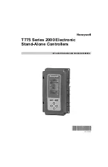
T775 SERIES 2000 ELECTRONIC STAND-ALONE CONTROLLERS

63-7147—05

10

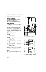
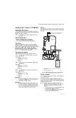
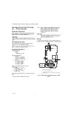
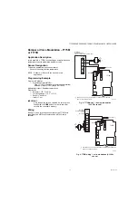
Chiller, Rotary Compressor – T775B

Application Description

The T775B is controlling the discharge water temperature of a 

rotary compressor. The T775B provides an optional low 

temperature or low pressure cut-out circuit.

NOTE: T775R reset models can also be used in this 

application.

Sensor Designation

This device application only requires one sensor. Sensor A is 

sensing discharge water and controls 1 or 2 compressors.

Operation

In this example, the cooling capacity of a Rotary Compressor 

is controlled by a slide valve, which when moved towards 

open or closed allows more or less refrigerant into the 

compressor. Open and Closed solenoid valves position this 

slide valve. The T775B is configured such that two relays are 

used to position a single slide valve in a floating mode by 

controlling the respective solenoid valves. Capacity of rotary 

compressors may also be controlled by variable speed drives, 

not covered here.

Programming Example

Relay 1: Compressor #1 controlling the Close solenoid valve

Program for: 

— Cool

— Setpoint = 52° F (11° C)

— Differential = 2° F (-17° C)

Relay 2: Compressor #1 controlling the Open solenoid valve

Program for: 

— Cool

— Setpoint = 56° F (13° C)

— Differential = 2° F (-17° C)

Relay 3: Compressor #2 controlling the Close solenoid valve

Program for: 

— Cool

— Setpoint = 56° F (13° C)

— Differential = 2° F (-17° C)

Relay 4: Compressor #2 controlling the Open solenoid valve

Program for: 

— Cool

— Setpoint = 60° F (16° C)

— Differential = 2° F (-17° C)

IMPORTANT

After the desired value is selected, be sure to press 

the 


or


or


HOME


button in order to save that 

value in the controller’s memory.

Wiring

All output relays should have a common power wiring source, 

which may or may not be the same as the T775 power wiring. 

See Fig. 5.

Fig. 5. T775B wiring — chiller, rotary compressor.

M24865

SENSOR A

(DISCHARGE WATER)

C

NO

NC

C

NO

NC

C

NC

NO

C

NC

NO

T  

RELAY

1

C

+

RELAY

4

RELAY

3

RELAY

2

T775B

COMPRESSOR

#2

CLOSE

SOLENOID

COMPRESSOR

#1

OPEN

SOLENOID

COMPRESSOR

#1

CLOSE

SOLENOID

OPEN SOLENOID

ENERGIZED

NULL

CLOSE SOLENOID

ENERGIZED

56°

52°

COOL MODE COMPRESSOR #1

OPEN SOLENOID

ENERGIZED

NULL

CLOSE SOLENOID

ENERGIZED

60°

56°

COOL MODE COMPRESSOR #2

F

A

L

L

T

E

M

P

E

R

A

T

U

R

E

R

I

S

E

T

E

M

P

E

R

A

T

U

R

E

R

I

S

E

T

E

M

P

E

R

A

T

U

R

E

F

A

L

L

T

E

M

P

E

R

A

T

U

R

E

L1

(HOT)

L2

COMPRESSOR

#2

OPEN

SOLENOID

120

COM

240

1

2

120  VAC

POWER WITH 24 VAC OR 120/240 VAC AT THE APPROPRIATE 

TERMINAL BLOCK.

24 VAC POWER TERMINAL BLOCK.

1

2

Summary of Contents for T775 Series 2000

Page 1: ...APPLICATION GUIDE AND CROSS REFERENCE 63 7147 05 T775 Series 2000 Electronic Stand Alone Controllers ...

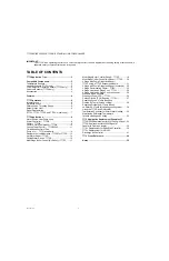
Page 2: ...ter Reset T775R 14 Chilled Water Reset T775R 16 Multi Stage Boiler Control No Reset T775P 17 Multi Stage Boiler Control Reset T775P 18 Multi Stage Chiller Control No Reset T775P 20 4 Stage with Pump Output and Reset T775P using a T775S Expansion Module 21 4 Stage with Pump Output and Reset continued 22 3 Stage Reciprocating Chiller T775L 23 4 Stage Heat and 6 Stage Cool T775L 24 4 Stage Heat and 6...

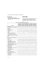
Page 3: ...nic Stand Alone Controllers Specification Data form 63 1318 COMPATIBLE COMPONENTS Temperature Sensors1 The controller accepts 1 097 Ohms PTC at 77 F 25 C 50021579 001 Standard sensor included with all models except T775U2006 and NEMA 4X models T775 SENS STRAP Strap on sensor with wiring box T775 SENS WR Water resistant with 5 foot leads included with NEMA 4X models T775 SENS WT Watertight with 6 f...

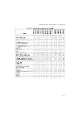
Page 4: ...ng Modulating Boiler Chiller Reset Stage Loop control of up to 12 relays Temperature humidity pressure or other application requiring 0 10 Vdc or 4 20 mA input Expansion module 4 relays per module 2 modules max Power 24 or 120 240 Vac with separate earth ground Relay Outputs SPDT Number of standard 1 2 4 2 4 4 0 4 2 4 2 4 4 4 2 2 0 2 4 Number of floating each floating output eliminates 2 relays 0 ...

Page 5: ...oints 1 2 4 2 4 4 2 6 4 6 4 1 4 6 4 2 2 4 n a Range 40 to 248 F 40 to 120 C Maximum high setpoint option irreversible n a Integral and Derivative Options Integral time selectable from 0 to 3 600 seconds n a Derivative time selectable from 0 to 3 600 seconds n a Staging Standard staging First on first off Equalized runtime On delay and Off delay between stages Time Clock Scheduler DST option n a 2 ...

Page 6: ...ect For all T775 Series 2000 controllers the derivative default value is factory set to zero no derivative control It is strongly recommended that the derivative remain at zero 0 unless you have a very good reason to adjust it Derivative control is not needed in the vast majority of HVAC applications Differential vs Throttling Range Differential is used for relay outputs and throttling range is us...

Page 7: ... single reset curve is programmed for the first output and is used by all outputs setup for Reset 2 For subsequent outputs a setpoint offset is used if that output is also being Reset When Reset is programmed the home screen conveniently displays the calculated Heat Cool setpoint s for the outputs based on the reset curve Setback Optional Description The Setback temperature option is available onl...

Page 8: ... rises to 96 F 36 C Relay 4 powers the high temperature alarm NOTE If no alarms are present relays 2 and 4 may be used as additional heating and cooling relays Programming Example Relay 1 Enables boiler circuit Program for Heat Setpoint 65 F 18 C Differential 10 F 12 C Relay 2 Low temperature alarm circuit Program for Heat Setpoint 55 F 13 C Differential 1 F 17 C Relay 3 Enables cooling circuit he...

Page 9: ...tial the sump water freeze up protection is provided by energizing Heating Relay 4 Programming Example Relay 1 Controlling spray water pump and or valve Program for Cool Setpoint 60 F 16 C Differential 5 F 12 C Relay 2 Controlling fan 1 Program for Cool Setpoint 65 F 18 C Differential 5 F 12 C Relay 3 Controlling fan 2 Program for Cool Setpoint 70 F 21 C Differential 5 F 12 C Relay 4 Controlling d...

Page 10: ... C Relay 2 Compressor 1 controlling the Open solenoid valve Program for Cool Setpoint 56 F 13 C Differential 2 F 17 C Relay 3 Compressor 2 controlling the Close solenoid valve Program for Cool Setpoint 56 F 13 C Differential 2 F 17 C Relay 4 Compressor 2 controlling the Open solenoid valve Program for Cool Setpoint 60 F 16 C Differential 2 F 17 C IMPORTANT After the desired value is selected be su...

Page 11: ...ol Sensor B IMPORTANT After the desired value is selected be sure to press the or or HOME button in order to save that value in the controller s memory IMPORTANT By programming the Relay 3 setpoint at 55 F 13 C the T775 is wired to cutoff power to the cooling fan Once the outside air temperature rises above 55 F 13 C relays 1 and 2 control the fan speed based on their setpoints for Sensor A Sump W...

Page 12: ...ontrol the device fan pump etc Program for Setpoint 0 F 17 C Differential 1 F 17 C Sensor Sensor B Setback 100 F 38 C Action Cool Now the relay will close at 6 00 a m and open at 6 00 p m daily 1 The date must be set before the time is set NOTE Keep in mind that if the scheduler is energized all relays will follow the time schedule If you do not want some outputs to go into a setback mode choose S...

Page 13: ...Throttling Range 10 F 12 C Sensor Sensor A Heat or Cool IMPORTANT After the desired value is selected be sure to press the or or HOME button in order to save that value in the controller s memory Wiring See Fig 8 and 9 for wiring connections for the T775M with examples of an MS75xx actuator and an ML7425 valve actuator Fig 8 T775M wiring damper modulation 2 10 Vdc shown Fig 9 T775M wiring valve mo...

Page 14: ... button in order to save that value in the controller s memory IMPORTANT By programming the boiler setpoint at 210 F 99 C the T775 has established 210 F 99 C as the highest operating point that will be allowed when the outside temperature falls below 20 F 7 C As the outside temperature increases above 20 F 7 C the boiler will be reset downward per the reset ratio until it reaches the minimum setpo...

Page 15: ...ure Sensor B NOTE The alternate Home screens do not show live updates of the sensor temperature They show the temperature only at the moment the button is pressed 1 From the Home screen use the button to verify the setpoint temperature for each output 2 Then press the HOME button to view the actual outside air temperature Sensor B Fig 14 Boiler discharge temperature setpoint vs outside temperature...

Page 16: ...Reset YES OTHER Relays 1 Relay 1 Reset YES OTHER Relay 1 Control to the chilled water temperature Program for Refer to the reset curve in Fig 15 Setpoint Max A1 Chiller 60 F 16 C Reset B1 Outside Min 70 F 21 C Setpoint Min A2 Chiller 45 F 7 C Reset B2 Outside Max 90 F 32 C Differential 10 F 12 C Cool IMPORTANT After the desired value is selected be sure to press the or or HOME button in order to s...

Page 17: ...reases additional stages of heat will cycle ON as the boiler water temperature decreases The T775P will stage three boilers to provide sufficient heating See Fig 18 The primary circulating pump energizes whenever any stage is energized Programming Example Program in Setup Press and hold the MENU button for 5 seconds to enter Setup mode Select the Outputs menu and then select Stages 3 T775 assigns ...

Page 18: ...rculating pump energizes whenever any stage is energized Programming Example Program in Setup Press and hold the MENU button for 5 seconds to enter Setup mode Select the Outputs menu and then select Stages 3 T775 assigns pump to Relay 4 Options Reset YES BOILER Options On Delay and Off Delay Seconds 0 to 3 600 default is 0 Options WWSD YES or NO Temperature 30 to 100 F 1 to 38 C STG4 Pump Relay 4 ...

Page 19: ...2 T775P wiring multi stage boiler control with reset THROTTLING RANGE 18 F 33 0 33 67 1 206 F 200 F 194 F 188 F M28043 STAGE 2 ON STAGE 3 ON STAGE 1 ON STAGES HYST STAGE 1 STAGE 2 STAGE 3 1 DISCHARGE WATER TEMPERATURE STAGE ENERGIZES STAGE DE ENERGIZES SENSOR B SP MAX A1 BOILER MAX SP MIN A2 BOILER MIN 200 140 10 SETBACK OFFSET 10 F OPTIONAL 190 20 30 40 50 60 70 F 80 150 160 170 210 220 180 F RES...

Page 20: ...s On Delay and Off Delay Seconds 0 to 3 600 default is 0 STG4 Pump Relay 4 controls the pump output 1 Enable YES Exercise YES or NO Prepurge 300 to 300 seconds default is 0 Postpurge 0 to 300 seconds default is 0 Return to the Setup menu and select Alarms Low Alarm YES Low Limit 54 F 12 C Stages 1 3 Control to the discharge water temperature Program for Setpoint 72 F 22 C Throttling Range 12 F 11 ...

Page 21: ...xpansion module is not needed Programming Example Program in Setup Press and hold the MENU button for 5 seconds to enter Setup mode Select the Outputs menu and then select Stages 4 T775 assigns pump to Relay 8 Options Reset YES BOILER STG8 Pump Relay 8 controls the pump output 1 Enable YES Exercise YES or NO Prepurge 300 to 300 seconds default is 0 Postpurge 0 to 300 seconds default is 0 Stages 1 ...

Page 22: ...perature It shows the tem perature only at the moment the button is pressed 1 From the Home screen use the button to verify the setpoint temperature for each output 2 Then press the HOME button to view the actual outside air temperature Sensor B Fig 28 Boiler discharge temperature vs outside temperature M24556 T775 BUS TERMINALS PROVIDE WIRING CONNECTIONS TO FROM T775P L AND T775S POWER WITH 24 VA...

Page 23: ...tton for 5 seconds to enter Setup mode Select the Outputs menu and then select Relays 3 Loops 1 Options DI Options Disable acts as low pressure cutoff Loop 1 Relays 3 Loop 1 Reset NO Loop 1 Chiller cooling Program for Setpoint 62 F 17 C Throttling Range 12 F 11 C Sensor A Cool Relay 4 Low temperature cutoff for freeze protection Program for Setpoint 40 F 4 C Differential 4 F 16 C Sensor B Heat IMP...

Page 24: ...range Programming Example Program in Setup Press and hold the MENU button for 5 seconds to enter Setup mode Select the Outputs menu and then select Relays 10 4 heat and 6 cool Loops 2 Loop 1 Relays 4 Loop 1 Reset NO1 Loop 2 Relays 6 Loop 2 Reset NO NOTES 1 The Integral setup parameter can be left at the factory default setting or adjusted as needed for each loop 2 The On Delay and Off Delay setup ...

Page 25: ...75S C NO NC C NO NC C NC NO C NC NO T T COOL 5 COOL 6 COM NO COM NO 1 3 2 T775 BUS TERMINALS PROVIDE WIRING CONNECTIONS TO FROM T775L AND T775S USE PIGTAIL CONNECTIONS TO WIRE THE T775 BUS TERMINALS ON THE FIRST T775S SECOND T775S MUST HAVE A JUMPER INSTALLED AS SHOWN AT THE JUMPER TERMINAL POWER WITH 24 VAC OR 120 240 VAC AT THE APPROPRIATE TERMINAL BLOCK 24 VAC POWER TERMINAL BLOCK 1 2 3 M27239 ...

Page 26: ...ep in mind these values are valid for proportional control and will differ in a PID loop where integral usually desired and derivative less often required are set to non zero values Integral and derivative time may need to be adjusted along with the throttling range Programming Example Program in Setup Press and hold the MENU button for 5 seconds to enter Setup mode and then select Sensors Sensor ...

Page 27: ...Programming Example Program in Setup Press and hold the MENU button for 5 seconds to enter Setup mode and then select Sensors Sensor A Type 0 10V Units PPM Minimum Value 0 0 Maximum Value 2000 NOTE Sensor A is a 0 10 Vdc CO2 sensor C7232 with a range of 0 to 2 000 PPM IMPORTANT After the desired value is selected be sure to press the or or HOME button in order to save that value in the controller ...

Page 28: ...to 50 F the zone temp needs to be 68 F Fig 34 Zone air reset curve Programming Example Program in Setup Press and hold the MENU button for 5 seconds to enter Setup mode Select the Outputs menu and then select RELAYS 2 LOOPS 1 LOOP 1 RELAYS 2 LOOP 1 RESET YES OTHER LOOP 1 Program for Refer to the reset curve in Figure 34 Setpoint Max A1 Zone Max 75 F 24 C Reset B1 Outside Min 50 F 10 C Setpoint Min...

Page 29: ... when the return air temp drops to 70 the discharge temp needs to be 60 Fig 36 Discharge air reset curve Programming Example Program in Setup Press and hold the MENU button for 5 seconds to enter Setup mode Select the Outputs menu and then select MOD 1 RESET YES OTHER MOD1 Program for Refer to the reset curve in Figure 36 Setpoint Max A1 Discharge Max 60 F 16 C Reset B1 Return Min 70 F 21 C Setpoi...

Page 30: ... RELAY 1 and RELAY 2 for reset SETUP OUTPUTS RELAY 1 RESET YES OTHER used only to set the dif ferential curve do not wire Relay 1 RELAY 2 RESET YES RELAY 3 RESET YES Press Home to exit Setup and press Menu to enter programming RELAY 1 The below settings for RELAY 1 are to establish the offset curve only There will not be any electrical connec tions to RELAY 1 Refer to reset curve in Fig 38 SP MAX ...

Page 31: ...9 T775R wiring diagram for solar water heating SENSOR A COLLECTOR WATER TEMP C NO NC C NO NC C NC NO C NC NO T T RELAY 1 C RELAY 4 RELAY 3 RELAY 2 M32046 T T SENSOR B STORAGE WATER TEMP 120 COM 240 FOR 240 VAC LOAD CONNECT TO 240 VAC TERMINAL 120V COM PUMP ALARM VALVE 1 1 ...

Page 32: ...d Setting up RELAY 1 and RELAY 2 for reset SETUP OUTPUTS RELAY 1 RESET YES OTHER used only to set the dif ferential curve do not wire Relay 1 RELAY 2 RESET YES used for cooling RELAY 3 RESET YES used for heating Press Home to exit Setup and press Menu to enter programming RELAY 1 The below settings for RELAY 1 are to establish the reset curve only There will not be any electrical connec tions to R...

Page 33: ...r W973A Logic Panel continues on the next page W973A T Y B W R T T 1 5 2 4 3 T1 R T7067 THERMOSTAT 1 5 2 4 3 8 7 6 SENSOR STAT 24V ECONO MOD HEAT MOD COOL WC BC RC RH BH WH W R L1 HOT L2 L1 HOT L2 R 1 HEAT 2 1 COOL 2 C 20 N H COOL 1 COOL 2 HEAT 2 HEAT 1 T675A HIGH LIMIT T675A COMPRESSOR LOCKOUT 1 1 POWER SUPPLY PROVIDE DISCONNECT MEANS AND OVERLOAD PROTECTION AS REQUIRED W973A SHOWN W973B HAS 3 HE...

Page 34: ... TERMINALS W AND R MINIMUM DRIVE CLOSED SIGNAL LESS THAN 0 17 VDC MAXIMUM DRIVE OPEN SIGNAL IS GREATER THAN 1 7 VDC USE SEPARATE TRANSFORMER FOR T775M WHEN USING 24 VAC A 250 OHM RESISTOR PROVIDES 40 AUTHORITY WHEN USING A 150 OHM MINIMUM POSITION POTENTIOMETER INSERT 340 OHM RESISTOR INCLUDED ACROSS TERMINALS R AND W POWER WITH 24 VAC OR 120 240 VAC AT THE APPROPRIATE TERMINAL BLOCK 24 VAC POWER ...

Page 35: ...nt for W973A Component Function W973A Logic Panel T775M2030 Replacement Thermostat T7067 Sensor A Room C7130B1008 Discharge Sensor C7046 Sensor B Discharge C7046D1008 Heating Cooling Motor M954 Series 90 4 20 mA 0 10 Vdc or 2 12 Vdc motor may be used Fan Start Fan Start Relay If a relay is available it can be used for fan control e g 1 stage Heat and 2 stage Cool using the T775M2030 Economizer M95...

Page 36: ...B R W C S V T T C SENSOR A STANDARD TEMPERATURE SENSOR C NO NC C NO NC C NC NO C NC NO RELAY 3 RELAY 2 RELAY 1 RELAY 4 120 COM 240 T T SENSOR B OUTDOOR SENSOR T775R 6 120 VAC 7 7 OTHER MOTORS SUCH AS 4 20 MA 0 10 VDC AND 2 10 VDC MAY BE USED ON THE MOD 1 OUTPUT TO VERIFY OUTPUT TEST OPEN CIRCUIT VOLTAGE BETWEEN THE MOD 1 TERMINALS W AND R MINIMUM DRIVE CLOSED SIGNAL LESS THAN 0 17 VDC MAXIMUM DRIV...

Page 37: ...re sensor See Temperature Sensors1 on page 3 Reset ratio and parallel shift n a Reset programming in the T775R provides the reset curve On Off motor control Jumper terminals 1 and 2 on the W964F If the W964F provided On Off motor control then wire motor to a relay output on the T775R to provide On Off control Actuator motor speed n a Use the Integral Time and Throttling Range to tune the T775R con...

Page 38: ...HES SHOWN WITH DEVICE ENERGIZED REFER TO SPECIFICATIONS FOR NUMBER OF SWITCHES AUXILIARY POTENTIOMETER ON S984J ONLY TERMINAL LABELED AUX THIS HOOKUP IS FOR A COOLING SYSTEM FOR A HEATING SYSTEM REVERSE W AND B WHEN SHIPPED LEADS ARE JOINED WITH A WIRE NUT TO DELAY STAGES ON REMOVE WIRE NUT FROM ORANGE AND WHITE LEADS AND CONNECT TO DELAY TIMER TO DELAY STAGES OFF REMOVE WIRE NUT FROM BLUE AND WHI...

Page 39: ...8018 T775 BUS TERMINALS PROVIDE WIRING CONNECTIONS TO FROM T775L AND T775S SETUP THE CONTROL T6031 OR T765 SO THAT IT CLOSES ON A TEMPERATURE FALL POWER WITH 24 VAC OR 120 240 VAC AT THE APPROPRIATE TERMINAL BLOCK 24 VAC POWER TERMINAL BLOCK 1 2 T775L T775S C NO NC C NO NC C NC NO C NC NO T T L1 HOT L2 24 VAC COM NO COM NO COM NO COM NO HEAT 2 HEAT 1 C NO NC C NO NC C NC NO C NC NO 3 120 VAC COOL ...

Page 40: ...trol Sensor A must always be the controlled temperature and Sensor B must always be the controlling temperature For example in a reset control based on outside temperature Sensor A must be the inside sensor and Sensor B must be the outside sensor Delay Timer S400A Use the On Delay and Off Delay programmable parameters of the T775L Throttling Range n a Set the programmable Throttling Range paramete...

Page 41: ...S AS SHOWN WHEN RESET NOT USED JUMPER TERMINALS 6 AND 7 SET HEAT AND COOL DISCHARGE SETPOINTS USING REMOTE SETPOINT POTENTIOMETERS TURN SETPOINT KNOB ON W7100 TO MINIMUM POSITION USE OF THE S963B1086 WILL CHANGE SETPOINT RANGE TO 40 TO 140 F GROUND CASE OF REMOTE SETPOINT POTENTIOMETER TO PREVENT PROBLEMS DUE TO STATIC ELECTRICITY WHEN CHANGEOVER TERMINALS 9 AND 10 ARE USED ON HEAT COOL MODELS JUM...

Page 42: ...next page M28018 T775 BUS TERMINALS PROVIDE WIRING CONNECTIONS TO FROM T775L AND T775S SETUP THE CONTROL T6031 OR T765 SO THAT IT CLOSES ON A TEMPERATURE FALL POWER WITH 24 VAC OR 120 240 VAC AT THE APPROPRIATE TERMINAL BLOCK 24 VAC POWER TERMINAL BLOCK 1 2 T775L T775S C NO NC C NO NC C NC NO C NC NO T T L1 HOT L2 24 VAC COM NO COM NO COM NO COM NO HEAT 2 HEAT 1 C NO NC C NO NC C NC NO C NC NO 3 1...

Page 43: ...omizer module e g W7212 to provide economization Heat Cool switch changeover T675A Connect the Digital Input terminal to an outdoor temperature control e g T6031 or T675A Program the Digital Input for Setback using 40 F 40 C for the T675A cooling setpoint to lock out the cooling system during cold weather Setpoint and Reset Setpoint and Reset dial Reset programming in the T775L provides the reset ...

Page 44: ...50 Johnson T775B2032 Johnson model Multiple SPDT temperature A350A B with up to 3 S350s Johnson T775B2040 Johnson model Multiple SPDT temperature A350A B with more than 3 S350s Johnson T775B2040 plus additional T775Bs as needed Johnson model Multiple SPDT temperature A350P Johnson T775M2006 Johnson model 1 mod temperature A350P with up to 2 S350s Johnson T775M2048 Johnson model 1 mod temperature w...

Page 45: ...ly 2 relays H775D1003 Honeywell 5 to 95 RH 2 SPDT T775U2006 5001774 001 H775E1002 Honeywell 5 to 95 RH 2 SPDT T775U2006 5001774 001 T4031A1008 Honeywell 30 to 50 SPST 5 ft T775A2009 5001774 001 T4031A1016 Honeywell 30 to 50 SPST 5 ft T775A2009 5001774 001 T4031A1073 Honeywell 30 to 90 SPST 8 ft T775A2009 5001774 001 T4031C1004 Honeywell 40 to 180 SPST 7 5 ft T775A2009 5001774 001 T4031C1012 Honeyw...

Page 46: ...T6031D1031 Honeywell 0 to 70 SPDT 5 5 ft T775A2009 5001774 001 T6031D1049 Honeywell 30 to 270 SPDT 5 5 ft T775A2009 5001774 001 T6031E1004 Honeywell 40 to 180 SPDT 5 5 ft T775A2009 5001774 001 T6031F1010 Honeywell 55 to 90 SPDT 5 5 ft T775A2009 5001774 001 T6031G1000 Honeywell 0 to 90 SPDT 6 ft T775A2009 5001774 001 T6031J1003 Honeywell 55 to 85 SPDT 5 5 ft T775A2009 5001774 001 T6031K1001 Honeywe...

Page 47: ...B1028 Honeywell 20 to 50 SPDT 10 ft T775A2009 5001774 001 Add S445A1010 to convert T775 to manual reset T675B1032 Honeywell 80 to 220 SPDT 10 ft T775A2009 50021579 001 x3 or C7031J2009 or C7100D1001 Averaging T678A1015 Honeywell 0 to 100 2 SPDT 20 ft T775B2032 5001774 001 T678A1080 Honeywell 160 to 260 2 SPDT 5 ft T775B2032 5001774 001 T678A1163 Honeywell 5 to 95 2 SPDT 20 ft T775B2032 5001774 001...

Page 48: ... T775F1089 Honeywell 20 to 220 3 SPDT T775M2030 T775G1005 Honeywell 20 to 220 3 SPDT T775M2014 T775G1013 Honeywell 20 to 220 3 SPDT T775M2014 T775G1021 Honeywell 20 to 220 3 SPDT T775M2014 T775G1039 Honeywell 20 to 220 4 SPDT T775M2014 T775J1001 Honeywell 20 to 240 1 SPDT T775R2035 T775J1019 Honeywell 20 to 240 None T775R2043 T775J1027 Honeywell 20 to 240 None T775R2043 T775J1035 Honeywell 20 to 2...

Page 49: ...2 123869A T775A2009 5001774 001 3 4 123870A A19AAF 21 Johnson 40 to 90 SPDT 6 ft T6031A1136 1 2 123869A T775A2009 5001774 001 3 4 123870A A19ACA 14 Johnson 30 to 100 SPST 6 ft L480G1044 20 to 60 F None T775A2009 5001774 001 Add S445A1010 to convert T775 to manual reset A19ACA 15 Johnson 30 to 100 SPST 10 ft L480G1044 None T775A2009 5001774 001 Add S445A1010 to convert T775 to manual reset A19ADB 1...

Page 50: ...12622AA T775B2024 5001774 001 T678 has no weatherproof enclosure 3 4 112630AA A28MA 1 Johnson 40 to 120 2 SPDT 6 ft T678A1437 0 to 100 F or T678A1445 55 to 175 F 1 2 112622AA T775B2024 5001774 001 T678 has no weatherproof enclosure 3 4 112630AA A28MA 2 Johnson 40 to 120 2 SPDT 6 ft T678A1437 0 to 100 F or T678A1445 55 to 175 F 1 2 112622AA T775B2024 5001774 001 T678 has no weatherproof enclosure 3...

Page 51: ...1073 1 2 123869A T775A2009 5001774 001 3 4 123870A 1609 103 White Rodgers 30 to 90 SPST 10 ft T4031A1073 8 ft cap 1 2 123869A T775A2009 5001774 001 3 4 123870A 1609 104 White Rodgers 30 to 90 SPST 20 ft T6031A1060 1 2 123869A T775A2009 5001774 001 3 4 123870A 1609 105 White Rodgers 30 to 90 SPST 5 ft T4031A1073 1 2 123869A T775A2009 5001774 001 3 4 123870A 1609 106 White Rodgers 30 to 90 SPST 5 ft...

Page 52: ...T 6 ft T6031A1136 30 to 90 F 1 2 123869A T775A2009 3 4 123870A TC 4111 020 Barber Colman 40 to 120 SPDT 20 ft T6031A1136 30 to 90 F 1 2 123869A T775A2009 5001774 001 3 4 123870A TC4112 Barber Colman 100 to 260 SPDT 6 ft L6008A1192 100 to 240 F 121371A T775A2009 TC4115 Barber Colman 40 to 120 SPDT 6 T6031A1136 30 to 90 F 1 2 123869A T775A2009 3 4 123870A TC4151 Barber Colman 70 to 120 SPDT 30 ft T4...

Page 53: ...o 60 SPDT 20 ft L480G1044 None T775A2009 5001774 001 Add S445A1010 to convert T775 to manual reset Ranco ETC 111000 Ranco T775A2009 ETC 111100 Ranco T775M2048 ETC 112000 Ranco T775M2048 ETC 112100 Ranco T775M2048 ETC 141000 Ranco T775B2016 ETC 211000 Ranco T775B2932 ETC 211100 Ranco T775M2048 ETC 212000 Ranco T775B2032 ETC 212100 Ranco T775M2048 ETC 24100 Ranco T775B2016 Table 6 Cross Reference Co...

Page 54: ...ion Floating Output Integral Voltage Options Type based Type based Type based Type based Type based Irreversible High Set Point Limit Lo Hi or Hi Lo staging Modulating Outputs T775M2048 T775R2027 T775R2027 Nema 4x Models T775B2016 Optional Input Sensor Outdoor Reset Power Supply Voltage 20 to 28 Vac 24 120 240 Vac 20 to 28 Vac 24 120 240 Vac 24Vac 24 120 240 Vac 24 120 240 Vac 120 Vac 24 120 240 V...

Page 55: ...55 63 7147 05 NOTES ...
Page 56: ...nal Inc 1985 Douglas Drive North Golden Valley MN 55422 Honeywell Limited Honeywell Limitée 35 Dynamic Drive Toronto Ontario M1V 4Z9 customer honeywell com U S Registered Trademark 2010 Honeywell International Inc 63 7147 05 M S Rev 10 10 Printed in U S A ...

Reviews: