T775 SERIES 2000 ELECTRONIC STAND-ALONE CONTROLLERS
63-7147—3
16
Chilled Water Reset – T775R
Application Description
The T775R is controlling the chiller water temperature, based
on outside temperature using a reset curve.
Multiple stages can also be controlled by using an offset from
the main setpoint for the subsequent relay outputs. When
enabling multiple stages for reset, each stage can have its
own programmable offset from relay 1 (stage 1).
Sensor Designation
This device application requires two sensors.
• Sensor A is sensing the water temperature of the chiller.
• Sensor B is sensing outside air temperature.
Operation
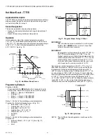
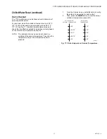
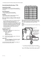
In this example, when the outside temperature reaches 90° F
(32° C), the desired water temperature of the chiller is
45° F (7° C). Likewise, when the outside temperature drops to
70° F (21° C), the chilled water temperature needs to be 60° F
(16° C).
Fig. 15. Chiller Reset Curve.
Programming Example
Program in Setup:
Press and hold the
MENU
button for 5 seconds to enter
Setup mode. Select the Outputs menu, and then select:
— MOD 1
→
Reset
=
YES-OTHER
— # Relays = 1
— Relay 1
→
Reset = YES-OTHER
Relay 1: Control to the chilled water temperature
Program for: (Refer to the reset curve in Fig. 15.)
— Setpoint Max A1 (Chiller) = 60° F (16° C)
— Reset B1 (Outside Min) = 70° F (21° C)
— Setpoint Min A2 (Chiller) = 45° F (7° C)
— Reset B2 (Outside Max) = 90° F (32° C)
— Differential = 10° F (-12° C)
— Cool
IMPORTANT
After the desired value is selected, be sure to press
the
#
or
$
or
HOME
button in order to save that
value in the controller’s memory.
IMPORTANT
By programming the Chiller setpoint at 45° F (7° C)
the T775 has established 45° F (7° C) as the lowest
operating control point that will be allowed during
reset with the above conditions satisfied.
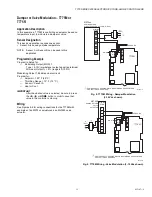
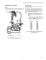
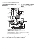
Wiring
All output relays should have a common power wiring source,
which may or may not be the same as the T775 power wiring.
Fig. 16. T775R Wiring - Chilled Water Reset.
NOTE: The Chilled Water Reset application continues on
the next page.
SENSOR B (OUTSIDE AIR)
SP MAX A1
SP MIN A2
70
90
°F
45
60
°F
RESET B1
(OUTSD MIN)
RESET B2
(OUTSD MAX)
SENSOR A
(CHILLER)
M24874
75
80
85
50
55
65
95
65
40
L1
(HOT)
L2
SENSOR A (CHILLED WATER)
C
NO
NC
C
NO
NC
C
NC
NO
C
NC
NO
T
T
RELAY
1
C
+
RELAY
4
RELAY
3
RELAY
2
T775R
CHILLER
M24875
T
T
SENSOR B
(OUTSIDE AIR)
120
COM
240
POWER WITH 24 VAC OR 120/240 VAC AT THE APPROPRIATE
TERMINAL BLOCK.
24 VAC POWER TERMINAL BLOCK.
1
1
2
120 VAC
2


