background image

T775P SERIES 2000 ELECTRONIC STAND-ALONE CONTROLLER

5

62-0256—11

Controller Wiring

WARNING

Electrical Shock Hazard.

Can cause severe injury, death or property 

damage.

Disconnect power supply before beginning wiring, 

or making wiring connections, to prevent electrical 

shock or equipment damage.

CAUTION

Do not use 24 Vac power to power any external 

loads if 120 Vac or 240 Vac is used to power 

the T775P.

CAUTION

A separate earth ground is required.

Equipment damage can result if the earth ground 

is not connected. See Fig. 7 and Table 2 on 

page 6.

CAUTION

Equipment Damage Hazard.

Electrostatic discharge can short equipment 

circuitry.

Ensure that you are properly grounded before 

handling the unit.

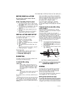
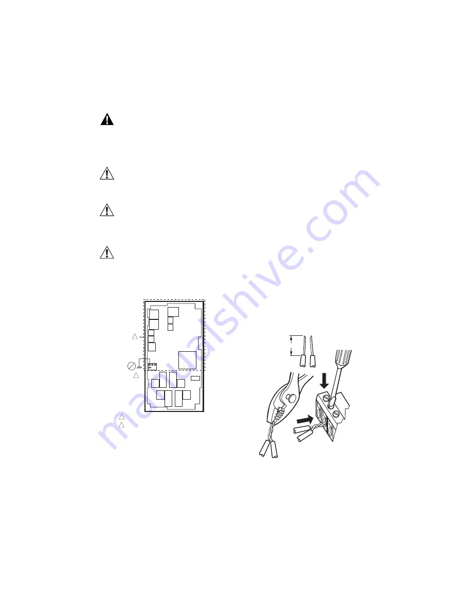
Fig. 5. Earth Ground.

IMPORTANT

Poor wiring practices can cause erratic readings 

from the sensor. To ensure proper operation, 

ensure that good mechanical connections are 

made to both the sensor and the controller.

IMPORTANT

When wiring the input power, only one source of 

power can be applied to the T775P (24, 120, or 

240 Vac). 

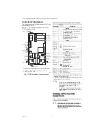
See Fig. 7 on page 6 for locating the appropriate power 

input, remote sensors input, low voltage, contact closure, 

and load output terminals. 

Access to the terminals can be gained through standard 

conduit knockouts (A through E in Fig. 7 on page 6

located around the perimeter of the enclosure:

• Knockouts A and B should be used only for sensor and 

low-voltage wiring.

• Knockouts C, D, and E can be used to gain access to 

the load relay output terminals and 120/240 Vac power 

wiring.

Controller Wiring Method

Wire the sensors and outputs, then wire the power 

connection.

Each terminal can accommodate the following gauges of 

wire:

• Single wire – from 14 AWG to 22 AWG solid or 

stranded

• Multiple wires – up to two 22 AWG stranded

For 24, 120, or 240 Vac power connections:

Single wire – from 14 to 18 AWG solid or stranded

Prepare wiring for the terminal blocks, as follows:

1.

Strip 1/2 in. (13 mm) insulation from the conductor.

2.

Cut a single wire to 3/16 in. (5 mm). Insert the wire 

in the required terminal location and tighten the 

screw.

3.

If two or more wires are being inserted into one ter-

minal location, twist the wires together a minimum 

of three turns before inserting them to ensure 

proper electrical contact.

4.

Cut the twisted end of the wires to 3/16 in. (5 mm) 

before inserting them into the terminal and tighten-

ing the screw.

5.

Pull on each wire in all terminals to check for good 

mechanical connection.

Fig. 6. Attaching two or more wires at terminal blocks.

C

+

W

1

2

M24296

NO HIGH VOLTAGE. CLASS 2 WIRING ONLY.

EARTH GROUND TERMINAL MUST BE CONNECTED  

TO CONDUIT CLAMP LOCALLY.

1

2

1/2 (13)

1.

  STRIP 1/2 IN. (13 MM) 

FROM WIRES TO 

BE ATTACHED AT 

ONE TERMINAL.

2.

 TWIST WIRES 

TOGETHER WITH 

PLIERS (A MINIMUM 

OF THREE TURNS).

3.

  CUT TWISTED END OF WIRES 

TO 3/16 IN. (5 MM) BEFORE INSERTING 

INTO TERMINAL AND TIGHTENING SCREW. 

THEN PULL ON EACH WIRE IN ALL 

TERMINALS TO CHECK FOR 

GOOD MECHANICAL CONNECTION.

M24382

Summary of Contents for T775P 2000 Series

Page 1: ...ORTANT The T775P is an operating control not a limit or safety control If used in applications requiring safety or limit controls a separate safety or limit control device is required Table 1 T775P Controller Configuration Controller Model Description Output Reset SPDT Relay Outputs Digital Output Digital Input Sensor Inputs Number of Sensors Included Stage Control Addable T775S Enclosure T775P200...

Page 2: ...nt sensor Accessories 107324A Bulb Holder duct insertion 107408 Heat Conductive Compound 4 ounce 50001774 001 Immersion Well stainless steel 304 1 2 in threading Product Changes Below are the changes to T775P model starting with Series 3 March 2009 Series 3 can be identified by the sideways 3 after the part number on the device label 1 Setpoint Enable and DHW options added to the DI options 2 Post...

Page 3: ... to cover it Mount the controller on any convenient interior location using the four mounting holes provided on the back of the enclosure using 6 or 8 screws screws are not provided and must be obtained separately Use controller dimensions in Fig 1 on page 2 as a guide The controller may be mounted in any orientation However mounting in the orientation shown in Fig 1 permits proper viewing of the ...

Page 4: ...st always be the controlled temperature and Sensor B must always be the controlling temperature For example in a reset control based on outside temperature Sensor A or C must be the inside sensor supply boiler chiller or return and Sensor B must be the outside sensor Multiple Parallel Sensors Multiple sensors can be parallel series wired to sense average temperatures in large spaces To maintain co...

Page 5: ...r sensor and low voltage wiring Knockouts C D and E can be used to gain access to the load relay output terminals and 120 240 Vac power wiring Controller Wiring Method Wire the sensors and outputs then wire the power connection Each terminal can accommodate the following gauges of wire Single wire from 14 AWG to 22 AWG solid or stranded Multiple wires up to two 22 AWG stranded For 24 120 or 240 Va...

Page 6: ...20 OR 240 VAC 1 2 C NO NC C NO NC C NC NO C NC NO C NO NC T T SENSOR A SENSOR B KNOCKOUT A DIGITAL INPUT POWER 120 240 VAC OUTPUT RELAY 2 KNOCKOUT D POWER 24 VAC OUTPUT RELAY 1 KNOCKOUT C KNOCKOUT E 1 OUTPUT RELAY 3 KNOCKOUT B T775 BUS OUTPUT RELAY 4 DIGITAL OUTPUT ALARM 2 T T SENSOR C T T C 120 COM 240 Table 2 Description of Wiring Terminal Connections Connection Termina l Description Sensors Sen...

Page 7: ...AC COM NO COM NO M24376 LOAD 2 LOAD 1 C NO NC C NO NC C T T SENSOR A SENSOR B T T T T SENSOR C L1 HOT L2 24 VAC M24377A C NO NC C NO NC C NC NO C NC NO COM LOAD 4 NO LOAD 3 LOAD 2 LOAD 1 C T T SENSOR A SENSOR B T T T T SENSOR C COM NO COM NO COM NO C NO NC C NO NC COM LOAD 2 LOAD 1 NO COM NO COM 120V M24389A 1 1 FOR 240 VAC LOAD CONNECT TO 240 TERMINAL C T T SENSOR A SENSOR B T T T T SENSOR C 120 ...

Page 8: ...he calibration value in the table exceeds the controller s calibration limits of 10 F 6 C you must use a heavier gauge wire For example with a wire run of 1 000 feet you must use 20 AWG wire or heavier to calibrate for wire loss within the limits of the controller See 1 2 2 2 CALIBRATE the sensor on page 14 for the instructions to enter the calibration value Fig 13 shows how sensor resistance vari...

Page 9: ...ny time exits the current Programming or Setup display screen and returns to the home screen as shown in Fig 14 and Fig 15 on page 10 Menu Button 1 Pressing the MENU button always displays the Program menu If you are in Setup mode you exit setup and return to the Program menu 2 Pressing and holding the MENU button for five seconds leaves the current screen and displays the Setup menu Left and Righ...

Page 10: ...s use the Left arrow button to scroll backward through the menus Right arrow button to select the highlighted menu item and display its content Up and Down arrow buttons and to scroll up and down through a list of items or to increase or decrease the value of a displayed parameter NOTE If you press the HOME button or there is no keypad activity for four minutes you exit Setup mode and return to th...

Page 11: ...ress all three buttons at exactly the same time for this action to occur IMPORTANT 1 This action sets the maximum setpoint value for all outputs to the setpoint high limit maximum 2 Setting the high limit setpoint maximum is irre versible If you perform the action inadvertently and this setpoint adversely affects the control of your system you must replace the controller Stages Relays and Pump Out...

Page 12: ...NU button you exit Setup mode and go to the Program menu Once in Setup mode you use the Left arrow button to scroll backward through the Setup menus Right arrow button to select the highlighted menu item and display its content Up and Down arrow buttons and to scroll up and down through a list of items or to increase or decrease the value of a displayed setup parameter Setup Procedure The Setup pr...

Page 13: ...p Sensors Sensor A Menu 1 2 2 SENSOR A If you are implementing two sensor reset control Sensor A supply or Sensor C return must always be the controlled temperature Normally Sensor A is used to sense the Supply temperature For example in a reset control based on outside temperature Sensor A or C must be the inside sensor and Sensor B must be the outside sensor 1 From the Sensors menu highlight SEN...

Page 14: ...efault For Sensor C the label names are Sensor Boiler Return and Chiller Return is the default 4 Use the button to accept the highlighted label and exit the list Fig 25 Setup Sensors Exit 1 2 2 4 Exit Sensor A Setup Press the button to exit the Sensor A selections and return to the Sensors menu or Use the and buttons to highlight EXIT and press the button Continue with 1 2 3 SENSOR B Fig 26 Setup ...

Page 15: ...es 1 3 1 Number of STAGES 1 From the Outputs menu use the and buttons to highlight STAGES 2 Press the button to display the number of stages 3 Use the and buttons to select the number of stages depending on setup See notes below Default 4 4 Press the button to accept the value and display the Outputs menu NOTE Up to two T775S Expansion Modules can be connected to a T775P making the following outpu...

Page 16: ...ns in the menu Fig 31 Setup Outputs Options Menu 1 3 3 OPTIONS 1 From the Outputs menu use the and buttons to highlight OPTIONS 2 Press the button to display the Options menu Fig 32 Setup Outputs Options Reset 1 3 3 1 RESET 1 From the Options menu use the and buttons to highlight RESET 2 Press the button to display the value Default NO 3 Use the and buttons to select the value 4 Press the button t...

Page 17: ...ror so you do not need to have a small throttling range to have accurate control Integral action allows for controlling to a setpoint even with a wide throttling range Fig 34 Setup Outputs Options Derivative 1 3 3 3 DERIVATIVE The Derivative default value is factory set to zero no derivative control It is strongly recommended that the derivative remain at zero 0 unless you have a very good reason ...

Page 18: ... press the button to display the value 2 Use the and buttons to select the value Default NO 3 Press the button to accept the value and display the Options menu If YES is selected the WWSD TEMP item appears in the Options menu Fig 38 Setup Outputs Options WWSD 1 3 3 7 WWSD TEMP The option for the warm weather shutdown temperature for stages displays when the WWSD option is selected as YES 1 From th...

Page 19: ...ugh 4 display on the home screen Fig 40 Setup Outputs Options DI Options 1 3 3 9 DI OPTIONS digital input options The DI Option that you select applies to all outputs This option overrides any Setpoint Setback values entered in the Schedule 1 Press the button to display the DI Option selections 2 Use the and buttons to highlight DISABLE SETBACK or IGNORE Default DISABLE 3 Press the button to accep...

Page 20: ...utputs menu use the and buttons to highlight the desired Stage 2 Press the button to display the selected Stage menu NOTES 1 Only the first four 4 stages have run time reset options 2 The relay outputs are used as stages with the last relay available to be configured as the pump output See Table 4 on page 11 3 STG4 PUMP changes to STG8 PUMP or STG12 PUMP when sequence modules are configured Fig 44...

Page 21: ...he and buttons to highlight the last Stage Fig 47 shows Stage 4 as the last relay output If used the pump output will be either 4 8 or 12 depending on the number of stages See 1 3 1 Number of STAGES on page 15 2 Press the button to display the Stage Pump menu NOTE Reset RT displays only if Show RT YES is selected during Output Options setup see Fig 41 Fig 48 Setup Pump Output 1 3 6 Enable Disable ...

Page 22: ...o accept the value When CONTNUOUS YES the pump runs continuously regardless of whether any stages are energized or not The pump shuts down only if the outside temperature exceeds the WWSD temperature setting If CONTNUOUS NO is selected then PREPURGE and POSTPURGE display on the Pump Out Options sub menu seeFig 49 Fig 52 Setup Pump Prepurge 1 3 7 3 PREPURGE 1 From the Stage Pump menu use the and bu...

Page 23: ...limit selection displays on the Alarms menu When an alarm is active the Digital Output D O closes and ALARM displays on the home screen NOTE Low and differential relay alarms require the condition to prevail for 5 minutes before contacts will close Fig 56 Setup High Alarm 1 4 1 HIGH ALARM Only Sensor A can be used to sense the high alarm temperature Sensor C cannot be used 1 From the Alarms menu u...

Page 24: ...efault NO 4 Press the button to accept the value and display the Alarms menu Selecting YES displays the LO LIMIT option on the Alarms menu once you exit this screen Continue with 1 4 2 1 LO LIMIT For systems with no low limit alarm select NO press the button and continue with 1 4 3 DIF ALARM on page 25 Fig 59 Setup Low Alarm Limit 1 4 2 1 LO LIMIT 1 From the Alarms menu use the and buttons to high...

Page 25: ...erature difference between Sensors A and C that causes the alarm to activate 1 From the Alarms menu use the and buttons to highlight DIF LIMIT 2 Press the button to display the differential alarm limit minimum temperature 3 Use the and buttons to increase decrease the temperature Default 30 F C Range 0 to 200 F 18 to 93 C 4 Press the button to accept the value and display the Alarms menu 5 Press t...

Page 26: ...ture desired is 160 F when the outdoor temperature is 70 F With the above settings example when the outdoor temperature is 50 F the effective setpoint is 180 F Setback Example Optional Setback of 10 F is used to drop the temperature at night by 10 F With the above settings example when the outdoor temperature is 50 F the effective setback setpoint is 170 F 180 F setpoint minus the 10 F setback CAU...

Page 27: ...at maximum 1 From the menu use the and buttons to high light RESET B1 or OUTSD MIN 2 Press the button to display the setpoint value 3 Use the and buttons to increase decrease the desired setpoint temperature Default 10 F 12 C Range 40 F to 248 F 40 C to 120 C 4 Press the button to accept the value and display the next option Fig 68 Program Sensor A Min Setpoint 2 2 3 SP MIN or BOILER MIN Setpoint ...

Page 28: ...o 66 C 4 Press the button to accept the value and display the next option Fig 71 Program Sensor Selection 2 2 6 SENSOR Select Sensor A to use the Supply sensor as the controlled temperature Select Sensor C to use the Return sensor as the controlled temperature 1 From the menu use the and buttons to high light SENSOR 2 Press the button to display the sensor selections 3 Use the and buttons to selec...

Page 29: ...e 150 F to 150 F 101 C to 66 C 3 Press the button to accept the value and display the Program menu 2 3 Exit Programming with Reset Press the HOME button to leave programming mode and return to the home screen This completes the programming procedure for a T775P controller that uses Reset 3 PROGRAMMING OUTPUT STAGE S WITH NO RESET The T775P can be programmed for Reset or No Reset From the factory t...

Page 30: ...accept the value and display the next option Fig 77 Program Sensor Selection 3 1 3 SENSOR Select Sensor A to use the Supply sensor as the controlled temperature Select Sensor C to use the Return sensor as the controlled temperature 1 From the menu use the and buttons to high light SENSOR 2 Press the button to display the sensor selections 3 Use the and buttons to select Sensor A or C Default Senso...

Page 31: ...conds select OUTPUTS select SCHEDULE and then select YES See 1 3 2 SCHEDULE on page 16 IMPORTANT To properly account for Daylight Saving time be sure to set the Date before setting the Time See 4 2 2 SET DATE on page 32 NOTE The T775P controller interface is intuitive You may want to use this procedure simply as a reference to locate the particular option or parameter of interest NOTES 1 If you pr...

Page 32: ...ute and AM PM 5 Press the button to accept the Time and return to the Options menu Fig 83 Schedule Options System Date 4 2 2 SET DATE Setting the system date is required to enable the controller to follow daylight saving time IMPORTANT To properly account for Daylight Saving time be sure to set the Date before setting the Time 1 From the Options menu use the and buttons to highlight SET DATE 2 Pre...

Page 33: ...ule menu for the selected time period For each selected time period the schedule event E1 and E2 parameters are exactly the same as shown in Fig 85 SCHEDULING EXAMPLE Setting the schedule is independent of the temperature settings for the relay outputs Table 5 illustrates a weekly schedule for daytime setpoint and night time setback use and shows the factory default settings To set a schedule cont...

Page 34: ...nd return to the selected time period menu 4 3 3 E2 SETPOINT setpoint for event 2 Creating the setpoint for event 2 is accomplished the same way as the first event See 4 3 1 E1 SETPT setpoint for event 1 4 3 4 E2 TIME time for event 2 Creating the time for event 2 is accomplished the same way as the first event See 4 3 2 E1 TIME time for event 1 4 3 5 EXIT exit from selected time period settings A...

Page 35: ...des an error message and diagnostic status as described below Error Message There is a two character error code that displays in response to controller software problems EE EEPROM Failure The values read back from the EEPROM are not the same as written into the EEPROM This error cannot be field repaired Replace the device Diagnostic Messages There are two diagnostic messages that can display in re...

Page 36: ...ass B digital device pursuant to Part 15 of the FCC rules These limits are designed to provide reasonable protection against harmful interference in residential installations This equipment generates uses and can radiate radio frequency energy and if not installed and used in accordance with the instructions may cause harmful interference to radio communications However there is no guarantee that ...

Reviews: