background image

T775R SERIES 2000 ELECTRONIC STAND-ALONE CONTROLLER

62-0249—13

2

Temperature Sensors

a

The controller accepts 1,097 Ohms PTC at 77° F (25° C):
• 50021579-001 – Standard sensor (2 standard sensors 

are included with each T775R model)

• T775-SENS-WR – Water resistant with 5 foot leads
• T775-SENS-WT – Watertight with 6 foot lead
• T775-SENS-OAT – Outdoor air temperature sensor
• C7031D2003 – 5 inch immersion sensor with wiring 

box (use immersion well; P/N 50001774-001)

• C7031J2009 – 12 foot duct averaging sensor with 

wiring box

• C7046D1008 – 8 inch duct probe with mounting flange
• C7100D1001 – 12 inch fast response, duct averaging 

sensor with flange

• C7130B1009 – Room mount sensor

Accessories

• 107324A – Bulb Holder, duct insertion
• 107408 – Heat Conductive Compound, 4 ounce

• 50001774-001 – Immersion Well, stainless steel 304, 

1/2 in. threading

Product Changes

Below are the changes to T775R models starting with 

Series 3 (March 2009). Series 3 can be identified by the 

sideways 3 after the part number on the device label.

1.

For the T775R2043 model only, the modulating high 

and low limit now both function in either the heat or 

the cool mode.

2.

MIN ON added.

3.

SYNC added.

4.

Differential and throttling range increased to 300°F.

5.

Setpoint and Enable options added to the DI 

options.

6.

HIDE option added to MOD1 and MOD2 (to hide 

them on the home screen).

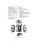
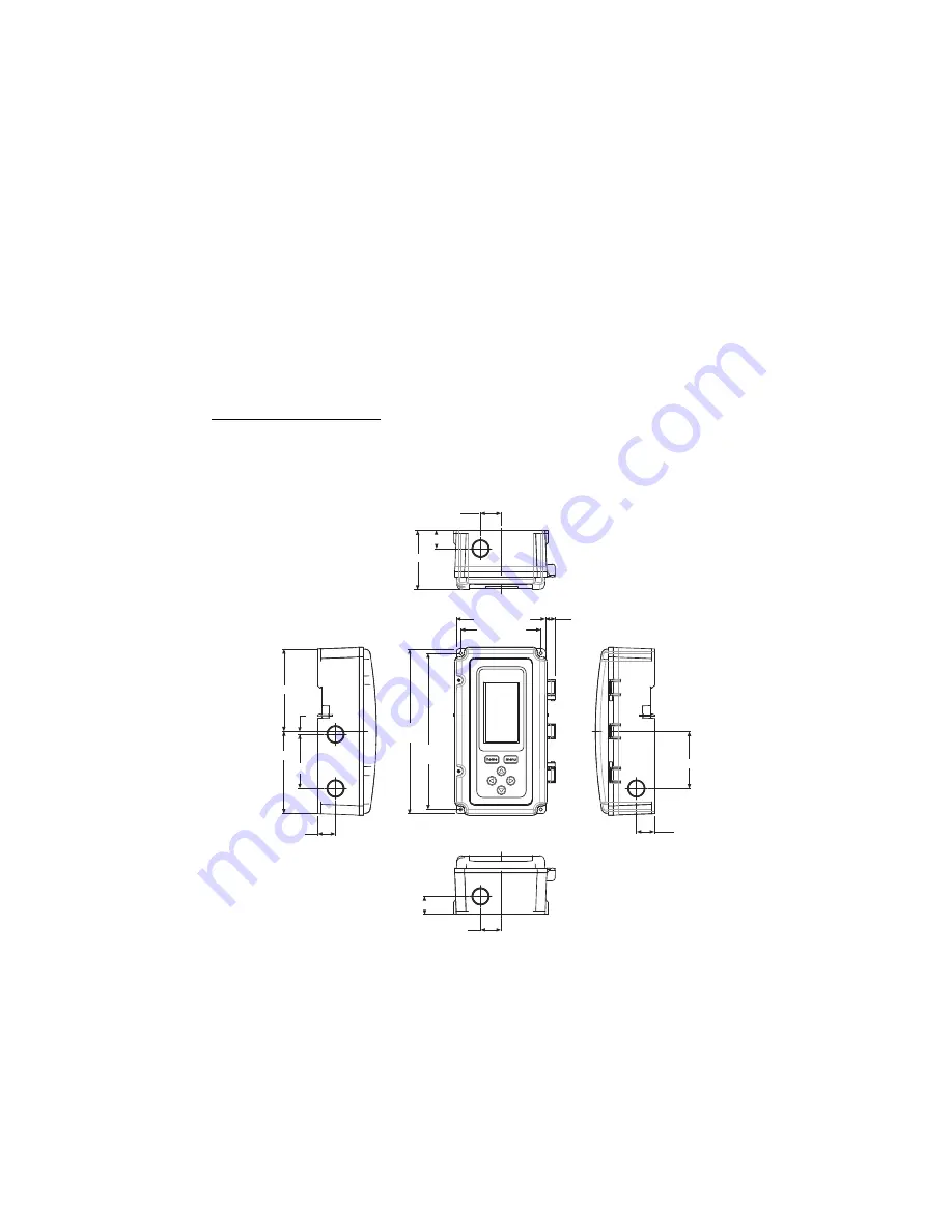
Controller Dimensions

Fig. 1. T775R Dimensions in inches (mm).

a

Refer to form 62-0265 – 

Temperature Sensors for the 

T775 Series 2000 Stand-alone Controller

4 13/32 (112.1)

1/2 (12.4)

3 31/32 (101)

7 23/32

(196)

8 5/32

(207.1)

2 15/16 (74)

7/8 (22.5)

1 (25.5)

4 1/16 (103.4)

4 1/16 (103.4)

1/64 (3.8)

2 11/16 (68.1)

7/8 (22.5)

2 13/16 (71.8)

7/8 (22.5)

1 (25.5)

7/8 (22.5)

M24279

TOP

BOTTOM

LEFT

RIGHT

FRONT VIEW

Summary of Contents for T775R 2000 Series

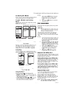
Page 1: ...ating control not a limit or safety control If used in applications requiring safety or limit controls a separate safety or limit control device is required Table 1 T775R Controller Configurations a All models include a digital input for use with the disable or setback option b The modulating analog outputs are 4 20 mA 0 10 Vdc 2 10 Vdc or Series 90 selectable c Each floating output eliminates two...

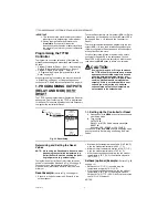
Page 2: ...001774 001 Immersion Well stainless steel 304 1 2 in threading Product Changes Below are the changes to T775R models starting with Series 3 March 2009 Series 3 can be identified by the sideways 3 after the part number on the device label 1 For the T775R2043 model only the modulating high and low limit now both function in either the heat or the cool mode 2 MIN ON added 3 SYNC added 4 Differential ...

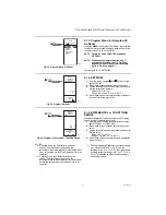
Page 3: ...sing the four mounting holes provided on the back of the enclosure using 6 or 8 screws screws are not provided and must be obtained separately Use controller dimensions in Fig 1 on page 2 as a guide The controller may be mounted in any orientation However mounting in the orientation shown in Fig 1 on page 2 permits proper viewing of the LCD display and use of the keypad Temperature Sensor s Mounti...

Page 4: ...t control Sensor A must always be the controlled temperature and Sensor B must always be the controlling temperature For example in a reset control based on outside temperature Sensor A must be the inside sensor and Sensor B must be the outside sensor Multiple Parallel Sensors Multiple sensors can be parallel series wired to sense average temperatures in large spaces To maintain control accuracy t...

Page 5: ... C D and E can be used to gain access to the load relay output terminals and 120 240 Vac power wiring Controller Wiring Method Wire the sensors and outputs then wire the power connection Each terminal can accommodate the following gauges of wire Single wire from 14 AWG to 22 AWG solid or stranded Multiple wires up to two 22 AWG stranded For 24 120 or 240 Vac power connections Single wire from 14 t...

Page 6: ...Stage Control 24 Vac Input and 24 Vac Load Table 2 Description of Wiring Terminal Connections Connection Terminal Label Description Sensors Sensor A T T Temperature Sensor polarity insensitive Sensor B Outputs Relay 1 Relay 2 Relay 3 Relay 4 NO COM NC 120 240 Vac Relay Output Mod 1 Vdc or mA W R B Series 90 a Modulating Output Mod 2 Input DI Digital Input dry contact 24 Vac Power 24V 24 Vac Hot Co...

Page 7: ...COM NO NO COM C NO NC C NO NC COM LOAD 2 LOAD 1 NO COM NO COM 120V M24287A 1 1 FOR 240 VAC LOAD CONNECT TO 240 TERMINAL C SENSOR A SENSOR B T T T T 120 COM 240 POWER SUPPLY L1 HOT L2 1 FOR 240 VAC LOAD CONNECT TO 240 TERMINAL SENSOR A SENSOR B T T T T C NO NC C NO NC C NC NO C NC NO COM 120V 1 M24288A LOAD 1 LOAD 3 LOAD 2 COM NO LOAD 4 C 120 COM 240 C NO NC C NO NC M31361 CLOSE RELAY TO DRIVE DEVI...

Page 8: ...ER TO POWER BOTH THE T775 AND THE MOTOR COMMONS ARE POLARITY SENSITIVE MOTORS MUST BE HALF WAVE RECTIFIED 1 HONEYWELL MODUTROL MOTOR WITH VOLTAGE CONTROL INPUT 1 F M29016 MODULATING OUTPUT TERMINAL MOD 1 B R W B R W TO VERIFY OUTPUT TEST OPEN CIRCUIT VOLTAGE BETWEEN THE MOD 1 TERMINALS W AND R MINIMUM DRIVE CLOSED SIGNAL LESS THAN 0 17 VDC MAXIMUM DRIVE OPEN SIGNAL IS GREATER THAN 1 7 VDC IF USING...

Page 9: ...troller s calibration limits of 10 F 6 C you must use a heavier gauge wire For example with a wire run of 1 000 feet you must use 20 AWG wire or heavier in order to calibrate for wire loss within the limits of the controller Refer to 3 2 2 2 CALIBRATE the sensor on page 20 for the instructions to enter the calibration value Table 3 Temperature Sensor Calibration for Resis tance Loss due to Wire Le...

Page 10: ...s to move your selection up and down through a menu or list When the desired item is highlighted you press the arrow button to display that item s content When a value is displayed e g 70 F 82 C the up and down arrows increase and decrease the value NOTE Once you select an item from a list or enter a value pressing the or or HOME button accepts your selection or value and stores it in the controll...

Page 11: ...meter of interest 2 The menus can display only those relays that are defined in Setup Refer to 3 3 4 NBR OF RELAYS on page 25 For example if you configure only two relays then only two relays display on the appropriate menus 3 If you press the HOME button or there is no keypad activity for four minutes you exit Program mode and return to the home screen 4 If you press the MENU button you exit Prog...

Page 12: ...will shift the reset curve up or down and cause the controlled setpoint to exceed either the entered reset max temp or min temp dropping below reset minimum is most common since setback is normally below setpoint If this is not desired either do not use setback or adjust the min and max values entered so that critical setpoints are not exceeded in the setback mode Fig 24 Reset Setup 1 1 Setting Up...

Page 13: ...ues in Fig 25 Fig 26 Program Menu 1 2 Entering Program Mode Press the MENU button then select PROGRAM and press the button to view the Program menu NOTE Modulating outputs are not available on controller models T775R2001 and T775R2035 Fig 27 Setpoint Values for Reset and Setback 1 2 1 Program Menus for Outputs with Reset Press the MENU button select PROGRAM then select RELAY 1 or MOD 1 to view the...

Page 14: ...nsor A B value when at SP MAX A1 Setpoint 1 From the menu use the and buttons to high light BOILER MIN or SP MIN A2 2 Press the button to display the setpoint value 3 Use the and buttons to increase decrease the desired minimum setpoint temperature Default 140 F 60 C Range 40 to 248 F 40 to 120 C 4 Press the button to accept the setpoint tempera ture and display the next option Fig 31 Program Sens...

Page 15: ...ss the button to display the heat and cool selections 3 Use the and buttons to select Heat or Cool 4 Press the button to accept the highlighted selec tion and display the Mod 1 menu 5 Use the and buttons to highlight EXIT 6 Press the button to accept the value and display the next option Fig 34 Program Setback 1 2 8 SETBACK OFFSET if configured The Setback temperature option displays only if sched...

Page 16: ... THROTTLING RANGE through 1 2 8 SETBACK OFFSET if configured beginning on page 15 1 3 Exit Programming with Reset When you finish programming all the outputs press the HOME button to leave programming mode and return to the home screen This completes the programming procedure for controllers that use Reset 2 PROGRAMMING OUTPUTS RELAY AND MOD WITH NO RESET Fig 37 Program Menu The T775R can be progr...

Page 17: ...the menu use the and buttons to high light DIFFRNTL or THROT RNG 2 Press the button to display the throttling range value 3 Use the and buttons to increase decrease the desired value Default 20 F 6 6 C Range 1 to 300 F 1 to 149 C 4 Press the button to accept the value and display the next option NOTES a In heating mode the Differential is below the setpoint The relay de energizes when the temperat...

Page 18: ...during setback mode for this output For example if your setpoint is 70 F 21 C and you want the temperature to drop 10 F 12 C during setback mode enter 60 F 16 C as the setpoint for this output 1 From the menu use the and buttons to high light SETBACK 2 Use the and buttons to increase decrease the desired setpoint temperature Default 60 F 16 C Range 40 to 248 F 40 to 120 C 3 Press the button to acc...

Page 19: ... move forward and backward through the menus NOTE The menus can display only those relays that are defined in Setup refer to 3 3 4 NBR OF RELAYS on page 25 For example if you configure only two relays then only two relays display on the appropriate menus To change the controller s sensors and output setup parameters perform the following procedures in the order listed 1 Enter Setup mode See 3 1 En...

Page 20: ...on page 9 1 From the Sensor A selections use the and buttons to highlight CALIBRATE 2 Press the button to display the calibration degree value 3 Use the and buttons to increase decrease the desired calibration degrees Default 0 0 Range 10 F 6 C 4 Press the button to accept the value and return to the Sensor A selections Fig 49 Setup Sensors Sensor A Label 3 2 2 3 LABEL the sensor input For a senso...

Page 21: ...Sensor B only Fig 51 Setup Sensors Sensor B Limit 3 2 3 3 LIMIT Sensor B only For the T775R2043 model only which has a High Low modulating temperature limit the LIMIT item displays on the Sensor B menu NOTE The LIMIT option acts only on Modulating Output 1 1 From the Sensors menu use the button to high light SENSOR B 2 Press the button to display the Sensor B menu 3 Use the and buttons to select t...

Page 22: ... positions the setpoint at the end of the throttling range For example with a high limit at Sensor B of 200 F 93 C and a throttling range of 10 F 12 C the modulating output controlling Sensor A begins to throttle back at 190 F 88 C and fully closes at 200 F 93 C Conversely the throttling range for the low limit begins above the setpoint in the same manner 1 From the Limit menu use the button to hi...

Page 23: ...utput prevents the output from dropping below the value entered This value can be useful to maintain minimum damper position Using the time clock or digital input to disable the output forces the output to 0 1 From the Mod menu use the and buttons to highlight MIN OUT 2 Press the button to display the Min Out 3 Use the and buttons to increase decrease the desired value from 0 to 100 in 1 increment...

Page 24: ... action allows for controlling to a setpoint even with a wide throttling range Fig 59 Setup Outputs Mod Out Derivative 3 3 3 1 4 DERIVATIVE The Derivative default value is factory set to zero no derivative control It is strongly recommended that the derivative remain at zero 0 unless you have a very good reason to adjust it Derivative control is not needed in the vast majority of HVAC applications...

Page 25: ... screen 1 From the Mod menu use the and buttons to highlight HIDE 2 Use the and buttons to highlight YES or NO Default YES 3 Press the button to accept the selection and return to the MOD menu NOTE The MOD1 and MOD2 outputs are still active even when hidden from the Home screen Fig 63 Setup Outputs Number of Relays 3 3 4 NBR OF RELAYS 1 From the Outputs menu use the and buttons to highlight RELAYS...

Page 26: ... 3 3 5 2 MIN OFF or MIN ON This is the minimum number of seconds of off time or on time for all relays 1 Press the button to display the Min Off On value 2 Use the and buttons to increase decrease the desired number of seconds from 0 to 990 seconds in 10 second increments Default 0 zero Range 0 to 990 seconds 3 Press the button to accept the seconds and dis play the DI OPTIONS NOTES a The minimum ...

Page 27: ... temperature without Reset Refer to Fig 43 on page 18 ENABLE energizes all relays and MOD outputs to 100 Use this option carefully DHW If a reset curve is being used then the controlled setpoint becomes the maximum setpoint either SP MAX A1 or BOILR MAX If a reset curve is not being used then DI closure for DHW has no effect IGNORE causes the digital input to have no effect on the Relay or Mod out...

Page 28: ...the Relays 1 From the Outputs menu use the and buttons to highlight the desired relay 1 4 depending on model 2 Press the button to display the selected relay menu The TYPE selection shown in Fig 70 displays only for Relay 1 and Relay 3 Continue with the remainder of this section to setup the relay outputs Fig 71 Setup Outputs Relay Type 3 3 6 1 TYPE standard or floating The Floating option is only...

Page 29: ...display the INTEGRAL option The actuator run time is defined as the time needed to move the actuator from the fully closed to fully open position and visa versa Fig 74 Setup Outputs Floating Relay Integral 3 3 6 1 1 2 INTEGRAL modulating floating relay only The Integral option displays only on the T775R2001 and the T775R2035 models when the Type option Floating 1 From the menu use the and buttons ...

Page 30: ...3 3 6 3 RESET The Reset menu displayed Fig 77 depends on whether the controller has modulating outputs For controllers with modulating outputs the first output MOD 1 is settable for Reset which then enables Reset to be set for the Relay outputs Refer to 3 3 3 1 6 RESET on page 25 For controllers with no modulating outputs this selection enables the controller s Reset function and allows each relay...

Page 31: ...me setback settings IMPORTANT To enable Scheduling you must first enter Setup mode press and hold the MENU button for 5 seconds select OUTPUTS select OPTIONS select USE SCHED and then select YES Refer to 3 3 5 1 USE SCHED on page 26 IMPORTANT To properly account for Daylight Saving time be sure to set the Date before setting the Time Refer to 4 2 2 SET DATE on page 33 NOTE The T775R controller int...

Page 32: ... Press the button to display the Options menu Fig 81 Schedule Options System Time 4 2 1 SET TIME Setting the system time is required to enable the controller to follow daylight saving time IMPORTANT Set the Date before setting the Time See 4 2 2 SET DATE on page 33 1 From the Options menu use the and buttons to highlight SET TIME 2 Press the button to display the current system time setting 3 Use ...

Page 33: ... 59 PM because setback starts at 6 00 PM b Setpoint time span is 6 00 PM until 5 59 AM because setback starts at 6 00 PM 4 3 Setting Individual Schedules As shown in the Schedule menu Fig 79 on page 32 schedules can be set for the following time periods Monday through Friday Saturday and Sunday Individual days of the week 1 From the Schedule menu use the and buttons to highlight the desired time p...

Page 34: ...r event 2 is accomplished the same way as the first event Refer to 4 3 1 E1 SETPT setpoint for event 1 on page 34 4 3 4 E2 TIME time for event 2 Creating the time for event 2 is accomplished the same way as the first event See 4 3 2 E1 TIME time for event 1 above 4 3 5 EXIT exit from selected time period settings After entering the time for event 2 use the button to exit the schedule time period a...

Page 35: ...gs are stored permanently Errors and Diagnostics The controller provides an error message and diagnostic status as described below Error Message There is a two character error code that displays in response to controller software problems EE EEPROM Failure The values read back from the EEPROM are not the same as written into the EEPROM This error cannot be field repaired Replace the device Diagnos...

Page 36: ...reasonable protection against harmful interference in residential installations This equipment generates uses and can radiate radio frequency energy and if not installed and used in accordance with the instructions may cause harmful interference to radio communications However there is no guarantee that interference will not occur in a particular installation If this equipment does cause interfere...

Reviews: