T775R SERIES 2000 ELECTRONIC STAND-ALONE CONTROLLER
29
62-0249—13
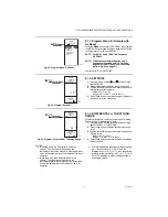
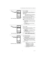
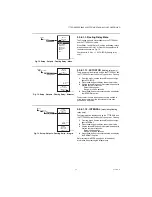
Fig. 72. Setup - Outputs - Floating Relay - Menu.
3.3.6.1.1. Floating Relay Menu
The Floating option is only available on the T775R2001
and the T775R2035 models.
When Relay 1 and/or Relay 3 is setup as floating, relays
are paired and the Float 1 or Float 2 menu displays with
the selections shown in Fig. 72.
Continue with “3.3.6.1.1.1. ACTUATOR (floating relay
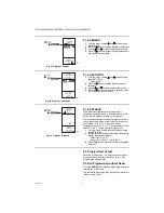
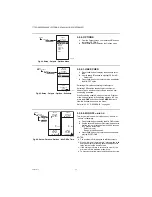
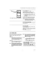
Fig. 73. Setup - Outputs - Floating Relay - Actuator.
3.3.6.1.1.1. ACTUATOR
(floating relay only)
The Actuator option displays only on the T775R2001 and
the T775R2035 models when the Type option = Floating.
1.
From the menu, use the
and
buttons to high-
light ACTUATOR.
2.
Press the
button to display the actuator value.
3.
Use the
and
buttons to increase/decrease the
desired number of seconds.
Default: 90 seconds
Range: 0 to 3,600 seconds
4.
Press the
button to accept the value and display
the INTEGRAL option.
The actuator run time is defined as the time needed to
move the actuator from the fully closed to fully open
position and visa versa.
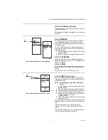
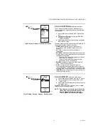
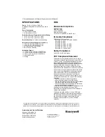
Fig. 74. Setup - Outputs - Floating Relay - Integral.
3.3.6.1.1.2. INTEGRAL
(
modulating/floating
relay only)
The Integral option displays only on the T775R2001 and
the T775R2035 models when the Type option = Floating.
1.
From the menu, use the
and
buttons to high-
light INTEGRAL.
2.
Press the
button to display the actuator value.
3.
Use the
and
buttons to increase/decrease the
desired number of seconds.
Default: 400 seconds
Range: 0 to 3,600 seconds
4.
Press the
button to accept the value and display
the DERIVATIV option.
Refer to Integral NOTES on page 24 for additional
information about setting the Integral time.
SETUP
OUTPUTS
FLOAT
1
SETUP
OUTPUTS
FLOAT 1
TYPE
ACTUATOR
INTEGRAL
DERIVATIV
SCHEDULE
RESET
EXIT
M24351
SETUP
OUTPUTS
FLOAT 1
ACTUATOR
ENTER
ACTUATOR
TIMING FOR
FLOAT 1
SETUP
OUTPUTS
FLOAT 1
ACTUATOR
90
SEC
M24352
SETUP
OUTPUTS
FLOAT 1
INTEGRAL
ENTER
INTEGRAL
TIME FOR
FLOAT 1
SETUP
OUTPUTS
FLOAT 1
INTEGRAL
400
SEC
M24353


