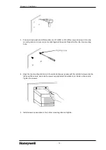
1. Connect a plug on one end of the adapter cable to one of the ports on the left side of the chassis
adapter. Be sure the plug is fully seated and tighten the plug screws to secure it.
2. Connect the plug on the other end of the adapter cable to the port under the left side of the
redundant power supply. Be sure the plug is fully seated and tighten the plug screws to secure it.
3. Repeat this procedure to connect the other adapter cable to the remaining port on the adapter and
to the second redundant power supply.
4. Go to the next section
Connecting optional annunciator cable
.
2.3.3
Connecting optional annunciator cable
Use the following procedure to connect a user-supplied cable between the solid-state relay on a
redundant power supply to an input module in the chassis. The normally open relay is held closed
during normal operation and opens when the power supply fails or is turned off.
ATTENTION
The annunciator output is rated for resistive loads. Do not use it to drive the coil of an
electromagnetic relay.
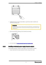
1. Open the redundant power supply door.
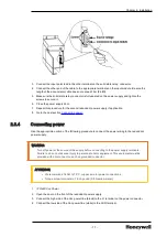
2. Connect the source voltage lead to one of the terminals on the solid-state relay connector, as
shown below. The source voltage must be compatible with the input module.
- 16 -
Chapter 2 - Installation


