background image

A

BOUT

T

HIS

D

OCUMENT

This document provides information for installing a redundant power supply for your C200 Controller
and/or I/O chassis.

1.1

Revision history

Revision

Date

Description

A

                                             August

20

20


Initial release of the

document.

- 4 -

CHAPTER

1

Summary of Contents for TC-RPCXX1

Page 1: ...EXPERION PKS RELEASE 516 Redundant Power Supply Installation Guide EPDOC X117 en 516A August 2020 ...

Page 2: ...al Sàrl While this information is presented in good faith and believed to be accurate Honeywell disclaims the implied warranties of merchantability and fitness for a purpose and makes no express warranties except as may be stated in its written agreement with and for its customer In no event is Honeywell liable to anyone for any direct special or consequential damages The information and specifica...

Page 3: ...ions 9 2 1 6 Tools needed 10 2 2 Installing Components 11 2 2 1 Installing redundant power supply 11 2 2 2 Installing redundant power supply chassis adapter 13 2 3 Connecting Components 14 2 3 1 General wiring guidelines 14 2 3 2 Connecting adapter cable 15 2 3 3 Connecting optional annunciator cable 16 2 3 4 Connecting power 17 Chapter 3 Operation 19 3 1 Activate Redundant Power Supply System 19 ...

Page 4: ...his document provides information for installing a redundant power supply for your C200 Controller and or I O chassis 1 1 Revision history Revision Date Description A August 2020 Initial release of the document 4 CHAPTER 1 ...

Page 5: ...l Hardware Installation Guide and confirmed that you have taken steps to minimize Electrostatic Discharge ESD CAUTION Since power output ratings vary for given approval bodies be sure the specified load capacity and temperature rating for the power supply will not be exceeded in your application For applicable power output rating specifications refer to the Experion specifications The Experion spe...

Page 6: ...ning with the prefix TK are for a coated version of the component Model Number Component Quantity per Chassis TC RPCXX1 or TK RPCXX1 120 240Vac Redundant Power Supply 21 TC RPDXX1 or TK RPDXX1 24Vdc Redundant Power Supply 21 TC RPSCA2 or TK RPSCA2 Redundant Power Supply Chassis Adapter 1 TC RPSC04 Redundant Power Supply Cables Length is 914mm 3ft 2 User Supplied2 12 14 AWG Annunciator Wiring Maxim...

Page 7: ...dant power supplies to the adapter 2 1 4 Verify mounting space requirements ATTENTION Be sure you meet these minimum spacing requirements when mounting components in an enclosure as shown in the following Figure l 10 2cm 4in between redundant power supplies and the enclosure l 2 55cm 1in between redundant power supplies l 15 3cm 6in between chassis and heat source l 5 1cm 2in between wireway and t...

Page 8: ...sis model in the following table to plan the panel layout for your particular installation See the Control Hardware Installation Guide for more chassis mounting information Chassis Model Dimensions All models Right Side View 8 Chapter 2 Installation ...

Page 9: ...TK FXX102 With Adapter installed TC FXX132 TK FXX132 With Adapter installed TC FXX172 With Adapter installed 2 1 5 Component layout recommendations We recommend that you use one of the following recommended layouts for installing redundant power supply components with one or two chassis Recommended Layouts With One Chassis 9 ...

Page 10: ...ne Chassis Recommended Layouts With Two Chassis 2 1 6 Tools needed l 1 8 inch flat blade screwdriver l 1 4 inch flat blade 2 or Phillips screwdriver l Needle nose pliers l Wire stripper l Electric drill 10 Chapter 2 Installation ...

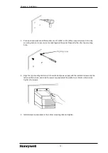
Page 11: ... can damage the backplane and cause intermittent operation 1 Reference the following mounting dimensions and measure and mark the location of the mounting tab holes for the power supply on the back panel Or if you have help position the power supply in the desired location on the back panel and use a center punch to mark the location of the mounting tab holes TIP The mounting hole dimensions for a...

Page 12: ...anel Repeat for the other top mounting hole 4 Align the top mounting tab holes in the redundant power supply with the installed screws slip the tabs over the screws and slide the power supply behind the washers so it rests on the screws Tighten the screws 5 Install screws and washers in the bottom mounting tabs and tighten 12 Chapter 2 Installation ...

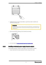
Page 13: ...abel The label protects the power supply from metal shavings falling inside it 7 Peel the protective label off the top of each redundant power supply 8 Go to the next section Installing redundant power supply chassis adapter 2 2 2 Installing redundant power supply chassis adapter Use the following procedure to install a chassis adapter on the left most side of a chassis 1 Align the right side of t...

Page 14: ...gether in any application For example do not run input power adapter cable and annunciator cable together in the same raceway l If the redundant power supply and the annunciator cable use the same input power source you can route the power line and annunciator cable together For example if your application uses a Vdc redundant power supply and the annunciator cable is connected to a Vdc input modu...

Page 15: ...unciator cable does not exceed 10m 32 8ft WARNING When components are located in a Division 2 hazardous location do not attempt to connect or disconnect cables unless power has been removed or the area is known to be nonhazardous 2 3 2 Connecting adapter cable Use the following procedure to connect the cable TC RPSC04 to the chassis adapter and the redundant power supply This procedure assumes tha...

Page 16: ...he next section Connecting optional annunciator cable 2 3 3 Connecting optional annunciator cable Use the following procedure to connect a user supplied cable between the solid state relay on a redundant power supply to an input module in the chassis The normally open relay is held closed during normal operation and opens when the power supply fails or is turned off ATTENTION The annunciator outpu...

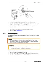
Page 17: ...cting power Use the appropriate portion of the following procedure to connect the power wiring to the redundant power supply WARNING Turn off power at the source of the supply before connecting to the power supply terminals Failure to do so could cause injury to personnel and or equipment This equipment must be provided with a disconnect on each ungrounded conductor ATTENTION l We recommend 14 AWG...

Page 18: ...door on the front of the redundant power supply 11 Connect the positive Vdc lead to the DC terminal on the power connector 12 Connect the negative Vdc lead to the DC terminal on the power connector 13 Connect the PE ground green with yellow stripe to the ground terminal Please refer to the Protective Earth PE ground guidelines and Ground bus connection guidelines in the Control Hardware Installati...

Page 19: ...1 1 Turn on power Open the door on the front of each redundant power supply and flip the power switch to the ON position Close the power supply door 3 1 2 Interpreting LED indications Each redundant power supply includes the following two diagnostic LEDs as shown in the following Figure l Power Green l Non Red non redundancy Amber 19 CHAPTER 3 ...

Page 20: ...ly is operating properly but is the only supply providing power to the chassis adapter Check the other supply Power Off Non red Solid Amber All possible connections are made but the redundant power supply is turned Off Turn the supply ON If the supply does not turn ON follow these steps 1 Remove input power to supply 2 Wait 15 minutes 3 Reconnect input power 4 Turn supply ON If the supply still do...

Page 21: ...r cable is not connected 5 The supply is ON but defective condition 1 Turn the supply ON 2 Verify that the line power is in the specified range If the LEDs remain Off cycle power 3 Verify that input power is supplied and turn ON the supply 4 Connect adapter cable and turn the supply ON 5 Replace the supply The redundant power supply chassis adapter has only one status LED as shown in the following...

Page 22: ...f any may be found in the materials accompanying the product in the documents or files accompanying such third party materials in a file named third_ party_licenses on the media containing the product or at http www honeywell com ps thirdpartylicenses Documentation feedback You can find the most up to date documents on the Honeywell Process Solutions support website at http www honeywellprocess co...

Page 23: ...te https www honeywellprocess com en US contact us customer support contacts Pages default aspx Training classes Honeywell holds technical training classes that are taught by process control systems experts For more information about these classes contact your Honeywell representative or see http www automationcollege com 23 ...

Reviews: