background image


65 

OPERATING INSTRUCTIONS & MAINTENANCE 

Reset Multi device 

To reset Multi device press for at least 3 seconds the 

SW7

 Reset 

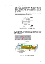
Button located on the upper left corner of the device.  


Figure 26 - Multi Reset button 

Switch off Multi device 

To switch off the unit, follow these steps: 

1.  Open the unit by unscrewing the four screws on the front cover 

(requires TORX Tamper-Resistant T10 screwdriver). 

2.  Unscrew the +Vcc wire on J2 connector or, if the device is 

supplied with POE/POE+, disconnect the Ethernet cable.  

Summary of Contents for Tema-Voyager Multi VMC Series

Page 1: ...1 Installation Manual Tema Voyager Multi VMC xx ...

Page 2: ...s may be stated in its written agreement with and for its customer In no event is Honeywell liable to anyone for any direct special or consequential damages The information and specifications in this document are subject to change without notice Trademarks Tema VoyagerTM is a trademark of Honeywell International Inc MIFARE is a registered trademark of Philips Electronics N V HID is a trademark or ...

Page 3: ...RS485 Data Cables for OSDP reader connection 15 Wiegand reader cables 16 Input wires 16 Output cable 16 MOUNTING THE DEVICE 17 Wall mount 17 DIN rail mount 18 IP32 protection mount 18 CONNECTING THE CABLES 20 Connecting the DC Power Supply 21 Connecting the network cable 22 Connecting the readers 24 Reader in position 1 26 Reader in position 2 26 Reader in position 3 27 Reader in position 4 27 RS4...

Page 4: ...s in 48 Connecting Fixed Outputs Plug in in slot of position 1 49 Fixed Output 1 49 Fixed Output 2 49 Fixed Output 3 50 Fixed Output 4 50 Connecting Configurable Outputs Plug in in slot of position 2 51 Configurable Output 3 51 Configurable Output 4 51 Configurable Output 5 52 Configurable Output 6 52 Connecting Configurable Outputs Plug in in slot of position 3 53 Configurable Output 1 53 Configu...

Page 5: ...7 PROTECTIVE FEATURES WARNING OF BYPASSING 68 TECHNICAL SPECIFICATIONS 69 REGULATIONS 71 CE Compliance 71 Access Control System for use in Security Applications Compliance 71 FCC Notice 72 Canadian and United States UL Listed 72 Australian CTick Conformity 73 RoHS compliance 73 WEEE compliance 73 China RoHS declaration 73 Appendix 1 Application switches 74 Appendix 2 Meaning of graphical symbols u...

Page 6: ...RCIAL CARRIER RESPONSIBLE FOR THE DAMAGE Electrostatic discharge Caution Electrostatic discharge ESD can damage integrated circuits and modules To prevent damage always follow these procedures Use static shield packaging and containers to transport all electronic components including completed reader assemblies Handle all ESD sensitive components at an approved static controlled workstation These ...

Page 7: ... do the following If shipping has caused damage to the unit file a claim with the commercial carrier If any other defect is apparent call for a return authorization Shipping instructions To ship equipment back to Temaline contact the customer service department at temaline orders honeywell com before returning the equipment When you call please have available A description of the problem or the re...

Page 8: ...USE INCIDENTAL CONSEQUENTIAL OR SPECIAL DAMAGES TO ANY PERSON RESULTING FROM THE USE OF TEMALINE S PRODUCTS Confidentiality All software drawings diagrams specifications catalogs literature manuals and other materials furnished by Honeywell HSG Temaline relating to the design use and service of the Products shall remain confidential and shall constitute the proprietary rights of Honeywell HSG Tema...

Page 9: ... one using Wiegand connection Doors can be managed with reader on one side and REX button on the other or with readers on both sides of the door The actual number of the readers managed by your device is based on the product you purchased see Contents of the box Multi device Multi has on board digital I O used for the management of the Wiegand reader buzzer green red led reader tamper and also 4 i...

Page 10: ...ction it connects Honeywell Enterprise Buildings Integrator EBI supervision center and in peer to peer other Temaline peripheral devices The external Power supply connection not required if the Multi device is supplied using POE or POE The Reader connections to connect Multi with third party readers Wiegand connection and RS485 OSDP connection Inputs outputs connections As part of the overall Tema...

Page 11: ...her information on the EBI Tema system complete commissioning steps and system configuration are included in the CD which is provided with EBI documentation package Tema Voyager Multi Web interface Guide User manual of the MULTI Web Interface used for commissioning and maintenance operations Tema Voyager Multi Quick Installation Guide It s the quick guide for the Multi installation it is included ...

Page 12: ...N1 Tema Voyager Multi 4 it manages up to 4 readers and I O Device support kit Code Qty Item P8160 5 4 Shunt Jumper 2PINS FEM 2 54mm 3 0A 55C to 105C 300 04883 12 Resistor CARB 392R 1 4W 1 THT LF White 300 04884 12 Resistor METAL 1K21 1 4W 1 THT LF Yellow 300 07677 4 Resistor CARB 270R 1 1 4W THT LF Blue P460 12 Diodes 1N4004 or equivalent 700 04116 1 Lower seal rubber to be used only when IP32 pro...

Page 13: ... kit 1 Mounting tools The following screwdrivers are required for the installation 3mm slotted screwdriver T10 Torx screwdriver Calculation of the current provided by Multi Multi device can be powered either with a 10V 30V DC power supply PoE or PoE each of these power sources can provide a different amount of current used to power the Multi device itself outputs readers and door locks directly su...

Page 14: ...et attached to this document Or Follow this hyperlink to retrieve the last version of the document from the EBI Global Support repository If you are reading this document in paper format go to EBI Global Support repository then into the Tech Tips section and download the Tema Voyager Multi Consumption Verifier spreadsheet xlsx Or Using your phone or tablet QR scanner follow the QR code of the spre...

Page 15: ...e shows the values for a single Multi device if more than one Multi needs to be connected to the same line divide the length by the number of the devices Network wire For POE and POE Cat5 or Cat6 Ethernet cable has to be used Readers wires RS485 Data Cables for OSDP reader connection Data cables used with RS485 must be twisted pair and with 120 ohm impedance Refer to Table 2 for the size of data c...

Page 16: ... Input wires Use a twisted pair cable for the contacts connections For outdoor wiring is mandatory to use shielded cables For internal wiring without shielded cables is recommended an electrical environment where the cables are well separated even at short runs especially to whom can be essentially subjected to interference The following table lists wire gauges and distances for Inputs Cable type ...

Page 17: ...he top and bottom side of the box To establish a common reference the Ethernet connector should be on the right bottom corner 2 Use the back case to mark the position of the 4 mounting holes Figure 4 Multi back case and holes positions 3 Drill the holes 4 Introduce M6 6 mm plastic dowels not included 5 Attach the back case to the wall No need to remove the board 6 Setup jumpers for the desired con...

Page 18: ...ld be on the right bottom corner 2 Plug the device back case on the DIN Rail use screw driver if you need to unplug it Figure 5 Multi DIN rail and unplug clip 3 Setup jumpers for the desired configuration 4 Connect the readers 5 Connect the inputs outputs 6 Connect the power supply of the device 7 Use screws to lock the cover of the device IP32 protection mount The Voyager Multi device can be moun...

Page 19: ...he longer one is for the top of the device where the shorter is for the bottom To wire the device when adhesive seals rubber are in place follow these steps 1 Using a screwdriver gently enlarge only the sealed holes need to be used 2 If the cable has stranded wires flexible core strongly twist the stripped portion of the wire in order to have a rigid tip before inserting it in the hole ...

Page 20: ...w what specified into IP32 protection mount chapter Cables to be connected are see Figure 6 Multi Wiring Diagram DC power supply only if the device is not supplied using POE POE Readers lines Ethernet 10 100 1G BaseT Input Outputs both Fixed and Configurable Figure 6 Multi Wiring Diagram ...

Page 21: ...t the DC Power supply cable heads onto the J2 terminal blocks use a 3mm slotted screwdriver 2 Connect the ground wire EGND Figure 7 Multi Power supply connections The J2 connector is provided of a polarized direct screw connector with the following connection characteristics Conductor section AWG min AWG24 max AWG16 Conductor rigid or flexible min 0 2 mm2 max 1 5 mm2 Check Once the DC Power Supply...

Page 22: ...he network cable must be a BaseT standard unshielded CAT5 or CAT6 cable terminated with an RJ45 male connector Select the network cable in compliance to what specified into the Network wire chapter on page 15 Plug the cable into the J4 connector Figure 9 Plug network connector Characteristics of the network connection are ...

Page 23: ...e Multi device switched on one of the two led LED2 or CR18 Ethernet physical link must be on Which led is switched on depends from the speed of the network LED2 green Ethernet 10 100 Mbit s CR18 green Ethernet 1 Gbit s The yellow LED1 Ethernet Communication activity must blink regularly Figure 10 Ethernet LED positions Check in case of use of POE or POE as power supply source once connected to Eth...

Page 24: ...sible to connect depends from the product code has been purchased see Multi device on page 12 The connection position of the readers depends as well from product code purchased Code Reader number Reader Connectors to be used VMC 01WENN1 1 reader Reader1 TB5 VMC 02WENN1 2 readers Reader1 TB5 and Reader2 TB6 VMC 03WENN1 3 readers Reader1 TB5 and Reader2 TB6 and Reader3 TB11 VMC 04WENN1 4 readers Rea...

Page 25: ... means that on a brand new device you need to change the reader configuration jumpers only if you need to connect OSDP readers The following pictures show for every reader position how to connect the reader device and how to set the reader configuration jumpers in case of Wiegand or OSDP reader Please note that to detect the tamper alarm of Wiegand reader it is required to insert closer to the rea...

Page 26: ...how the connections schematics and jumpers setting for reader in position 1 Wiegand reader OSDP reader Reader in position 2 The below pictures show the connections schematics and jumpers setting for reader in position 2 Wiegand reader OSDP reader ...

Page 27: ...how the connections schematics and jumpers setting for reader in position 3 Wiegand reader OSDP reader Reader in position 4 The below pictures show the connections schematics and jumpers setting for reader in position 4 Wiegand reader OSDP reader ...

Page 28: ... connected to select RS 485 matched distance mode Multi supports biasing and end of line termination for the RS 485 network Please refer chapter Switches and LEDs on page 61 for the position of the switches For every reader there are two switches one for Data A and one for Data B that need to be set both in the same way When switch is OFF terminator resistor is not inserted RS 485 allows the wirin...

Page 29: ...esistor not inserted OFF Reader4 SW6 1 RS485 termination resistor Data A ON termination resistor inserted OFF termination resistor not inserted OFF SW6 2 RS485 termination resistor Data B ON termination resistor inserted OFF termination resistor not inserted OFF Table 4 RS485 Terminator resistor switches Connecting Inputs Multi provides four fixed inputs and other eight lines can be freely configu...

Page 30: ... The below pictures show the connections schematics for dry contact and supervised contact for fixed input 1 Dry contact connection Supervised connection Fixed Input 2 The below pictures show the connections schematics for dry contact and supervised contact for fixed input 2 Dry contact connection Supervised connection ...

Page 31: ... for dry contact and supervised contact for fixed input 3 Dry contact connection Supervised connection Fixed Input 4 The below pictures show the connections schematics for dry contact and supervised contact for fixed input 4 Dry contact connection Supervised connection ...

Page 32: ...hematics for dry contact and supervised contact for configurable input 1 Dry contact connection Supervised connection Configurable Input 2 The below pictures show the connections schematics for dry contact and supervised contact for configurable input 2 Dry contact connection Supervised connection ...

Page 33: ...y contact and supervised contact for configurable input 3 Dry contact connection Supervised connection Configurable Input 4 The below pictures show the connections schematics for dry contact and supervised contact for configurable input 4 Dry contact connection Supervised connection ...

Page 34: ...y contact and supervised contact for configurable input 5 Dry contact connection Supervised connection Configurable Input 6 The below pictures show the connections schematics for dry contact and supervised contact for configurable input 6 Dry contact connection Supervised connection ...

Page 35: ...contact for configurable input 8 Dry contact connection Supervised connection Caution Temaline recommends that you establish an electrical environment where the cables are well separated even at short runs especially for the power cables or external cables which can be essentially subjected to interference or lightning Use a twisted pair cable for the contact cables Make sure that the cables corre...

Page 36: ...case of external relay powered directly from Multi and with relay powered from an external power supply for both fixed output and for configurable ones Note Use 12VDC relay max coil current 50mA each In this case it s mandatory to connect a 1N4004 diode as shown into schematics Multi can also be equipped with optional VMA 06 or VMA 07 relay plugs in see chapter USING RELAYS PLUGS IN VMA 06 VMA 07 ...

Page 37: ... power supply using fixed output 1 External Relay Powered by Multi External relay powered by external power supply Fixed Output 2 The below pictures show the connections schematics for an external relay powered directly from Multi or from an external power supply using fixed output 2 External Relay Powered by Multi External relay powered by external power supply ...

Page 38: ...y using fixed output 3 External Relay Powered by Multi External relay powered by external power supply Fixed Output 4 The below pictures show the connections schematics for an external relay powered directly from Multi or from an external power supply using fixed output 4 External Relay Powered by Multi External relay powered by external power supply ...

Page 39: ...wer supply using configurable output 1 External Relay Powered by Multi External relay powered by external power supply Configurable Output 2 The below pictures show the connections schematics for an external relay powered directly from Multi or from an external power supply using configurable output 2 External Relay Powered by Multi External relay powered by external power supply ...

Page 40: ... configurable output 3 External Relay Powered by Multi External relay powered by external power supply Configurable Output 4 The below pictures show the connections schematics for an external relay powered directly from Multi or from an external power supply using configurable output 4 External Relay Powered by Multi External relay powered by external power supply ...

Page 41: ... configurable output 5 External Relay Powered by Multi External relay powered by external power supply Configurable Output 6 The below pictures show the connections schematics for an external relay powered directly from Multi or from an external power supply using configurable output 6 External Relay Powered by Multi External relay powered by external power supply ...

Page 42: ... configurable output 7 External Relay Powered by Multi External relay powered by external power supply Configurable Output 8 The below pictures show the connections schematics for an external relay powered directly from Multi or from an external power supply using configurable output 8 External Relay Powered by Multi External relay powered by external power supply ...

Page 43: ...ED to monitor the Outputs state To be able to use this check the outputs must be properly configured and the Multi switched on Green color indicates output active where LED switched off means output not configured or inactive Figure 13 Outputs monitor LED ...

Page 44: ...e connection for an input that drives the cut of the power supply of the device in case of emergency Up to 3 relay output plugs in can be connected to Multi These are the product codes and the characteristics of the plugs in Code Item VMA 06 Tema Voyager Multi Relay Output board provides 4 Relay Output dry contact NO NC 24V 3A VMA 07 Tema Voyager Multi Emergency Relay Output board provides 4 Relay...

Page 45: ...Determine an appropriate mounting position for the plugs in If you have a VMA 07 you have to plug it only on the position 1 where VMA 06 can be plugged in any of the 3 sockets positions in relation to the outputs to be managed a Position 1 drives fixed outputs 1 2 3 4 b Position 2 drives flexible outputs 3 4 5 6 c Position 3 drives flexible outputs 1 2 7 8 ...

Page 46: ...lugging the VMA 06 on position 1 Caution The plugin has two connectors one with 8 pins and another with 6 pins this has to be matched with the socket on the main board 5 Set the jumpers required to configure the use of the plug in see for details Configuration of Multi to use VMA 06 and VMA 07 plugs in on page 48 6 Wire the outputs as specified in the following of the chapter ...

Page 47: ...umpers block and outputs based on the position of the plug in on the board Figure 18 Jumpers blocks on plugs in Plug in position Outputs match 1 P5 Fixed output1 P3 Fixed output2 P4 Fixed output3 P6 Fixed output4 2 P5 Line3 P3 Line4 P4 Line5 P6 Line6 3 P5 Line1 P3 Line2 P4 Line7 P6 Line8 Table 5 Matches between jumpers blocks and outputs Specific position of jumpers on the jumper block is used to ...

Page 48: ...7 plugs in To use relay outputs on VMA 06 and VMA 07 plugs in it is required to properly configure the jumpers on Multi board In the following pictures we show all the possible configuration of Multi to use plugs in relay outputs For every configuration is shown also the related Jumper settings Caution After inserting VMA 06 and VMA 07 plugs in it is required to configure some jumpers on Multi boa...

Page 49: ...in the same way for VMA 06 and VMA 07 VMA 06 or VMA 07 plug in must be inserted in slot 1 Fixed Output 1 Door Lock Powered by Multi relay Door lock powered by external power supply and driven by Multi relay Relay output mode Power Output NO as in above picture or NC Relay output mode Dry Contact NO as in above picture or NC Fixed Output 2 Door Lock Powered by Multi relay Door lock powered by exter...

Page 50: ...e Power Output NO as in above picture or NC Relay output mode Dry Contact NO as in above picture or NC Fixed Output 4 Door Lock Powered by Multi relay Door lock powered by external power supply and driven by Multi relay Relay output mode Power Output NO as in above picture or NC Relay output mode Dry Contact NO as in above picture or NC ...

Page 51: ...n must be inserted in slot of position 2 Configurable Output 3 Door Lock Powered by Multi relay Door lock powered by external power supply and driven by Multi relay Relay output mode Power Output NO as in above picture or NC Relay output mode Dry Contact NO as in above picture or NC Configurable Output 4 Door Lock Powered by Multi relay Door lock powered by external power supply and driven by Mult...

Page 52: ...e Power Output NO as in above picture or NC Relay output mode Dry Contact NO as in above picture or NC Configurable Output 6 Door Lock Powered by Multi relay Door lock powered by external power supply and driven by Multi relay Relay output mode Power Output NO as in above picture or NC Relay output mode Dry Contact NO as in above picture or NC ...

Page 53: ...n must be inserted in slot of position 3 Configurable Output 1 Door Lock Powered by Multi relay Door lock powered by external power supply and driven by Multi relay Relay output mode Power Output NO as in above picture or NC Relay output mode Dry Contact NO as in above picture or NC Configurable Output 2 Door Lock Powered by Multi relay Door lock powered by external power supply and driven by Mult...

Page 54: ...e Power Output NO as in above picture or NC Relay output mode Dry Contact NO as in above picture or NC Configurable Output 8 Door Lock Powered by Multi relay Door lock powered by external power supply and driven by Multi relay Relay output mode Power Output NO as in above picture or NC Relay output mode Dry Contact NO as in above picture or NC ...

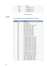
Page 55: ...sed to cut the power of the door lock This can be used in case of emergency like a fire alarm The J1 terminal block is opto isolated this allows connecting simultaneously several emergency Inputs Figure 26 VMA 07 Emergency input The two wires must enter in the Multi case from the two holes located on the right of the first group of holes on the bottom of the device see picture Figure 27 Emergency ...

Page 56: ...Close the device cover 3 Secure the cover by mean of the 4 torx screws see Figure 20 this operation requires a TORX anti tamper T10 screwdriver Figure 20 Multi cover Commissioning tips Commissioning of the device is outside the scope of this manual never the less we will include here some tips on this activity addressing you to the EBI documentation for the full details EBI Temaline Access Control...

Page 57: ...Device Factory FW version A device is shipped from factory with a running version of the FW application corresponding to the most recent version available at the manufacturing time of the released FW The installed version may not be suitable for your plant or a more recent version of the FW could be available You should verify the FW version installed on your device and check the Temaline compatib...

Page 58: ... it case Figure 21 Photo of Multi device board Figure 22 provides a graphical representation of the MULTI device and of the boards Main board and VMA 0x plugs in VMA 06 VMA 06 VMA 06 VMA 07 MULTI Enclosure Figure 22 Graphical representation of Multi device and VMA 0x plugs in ...

Page 59: ...rminal Blocks The below table lists the terminal blocks and explain their meaning Terminal Block Meaning TB1 Configurable I O line 1 TB2 Configurable I O line 2 TB3 Configurable I O line 3 TB4 Configurable I O line 4 TB5 Reader1 TB6 Reader2 TB7 Fixed Input 1 and Fixed Output 1 TB8 Fixed Input 2 and Fixed Output 2 TB9 Fixed Input 3 and Fixed Output 3 TB10 Fixed Input 4 and Fixed Output 4 TB11 Reade...

Page 60: ...tput 1 relay selector P13 Configurable Output 3 relay selector P14 Configurable Output 3 relay selector P15 Configurable Output 8 relay selector P16 Configurable Output 8 relay selector P17 Configurable Output 7 relay selector P18 Configurable Output 7 relay selector P19 Configurable Output 2 relay selector P20 Configurable Output 2 relay selector P21 Configurable Output 6 relay selector P22 Confi...

Page 61: ...ctor P40 Reader 4 Wiegand OSDP selector Table 7 Jumpers Switches and LEDs Figure 33 Switches and LEDs Switches The below table lists the switches and explain their meaning Switch Function Default SW1 1 Application Switches Spare SW1 2 Application Switches FW application roll back See Appendix 1 for details Open SW1 3 Application Switches Restore Factory See Appendix 1 for details Open SW1 4 Applic...

Page 62: ...d OFF termination resistor not inserted Open SW5 1 RS485 Reader 3 termination resistor Data A ON termination resistor inserted OFF termination resistor not inserted Open SW5 2 RS485 Reader 3 termination resistor Data B ON termination resistor inserted OFF termination resistor not inserted Open SW6 1 RS485 Reader 4 termination resistor Data A ON termination resistor inserted OFF termination resisto...

Page 63: ...ivity Green Blinking when RX or TX is active OFF no RX TX activity RJ45 2 Ethernet physical link 1G bit s Yellow ON Good link OFF no link or no 1G bit s LED1 Configurable I O 1 Green LED ON Output OFF Input LED2 Configurable I O 2 Green LED ON Output OFF Input LED3 Configurable I O 3 Green LED ON Output OFF Input LED4 Configurable I O 4 Green LED ON Output OFF Input LED5 Configurable I O 5 Green L...

Page 64: ...vice From factory and when external tamper is not used P1 is closed with a jumper Figure 24 External Tamper Connector If you need to connect an external tamper to the connector P1 you can use the below schematic Figure 25 External tamper connection schema Please note that P1 and the device anti open tamper are in series and thus it is not possible to distinguish which of the two tampers raised the...

Page 65: ...per left corner of the device Figure 26 Multi Reset button Switch off Multi device To switch off the unit follow these steps 1 Open the unit by unscrewing the four screws on the front cover requires TORX Tamper Resistant T10 screwdriver 2 Unscrew the Vcc wire on J2 connector or if the device is supplied with POE POE disconnect the Ethernet cable ...

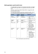
Page 66: ... 1 OFF No Ethernet communication Check the Ethernet wiring Check the status of the network Application running CR78 OFF Application not running Reset the device using reset button EBI communication CR96 ON No communication with EBI Check if the supervision centre is up and running Check if the Multi device is properly configured into EBI Check the Ethernet communication Data Base status CR25 ON Da...

Page 67: ...ributed to the contact detector this can damage the detector or create a short circuit Power supply Output alarm will be activated Check the cabling before to switch on the main power Connect the output port to input port Input short cut alarm is activated Check the cabling before to switch on the main power Plug in inserted in a reverse way The protection inside the Multi will avoid permanent dam...

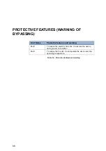
Page 68: ...ame Protective features and warning Multi To reduce the electric shock risk do not wire the device during power on condition Multi To reduce the fire risk do not operate the device over the operating temperature Table 12 Protective features and warning ...

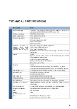
Page 69: ... for each input Voltage 14V maximum 0V minimum Min detection time 50ms Outputs 4 fixed From the main Board Power Open Drain Mosfet 12V 50mA From the optional Relay Output board dry contact NO NC 24V 3A Input Output lines 8 configurable same characteristics of the fixed input output Technical Microprocessor Freescale i MX 6 SOLO 800 Mhz Operative system LINUX Flash Memory High reliability NOR Flash...

Page 70: ... screw 4 Torx screws Anti Tampering 1 internal switch against opening Environmental Protection level IP32 Environmental temperature for correct operation 10 C to 55 C Storage temperature 25 C 70 C Storage and operating humidity 0 95 not condensing ...

Page 71: ...dards EN 50130 4 2011 A1 2014 EN 55032 2012 AC 2013 EN 60950 1 2006 A11 2009 A1 2010 A12 2011 A2 2013 EN 50581 2012 Access Control System for use in Security Applications Compliance Company name Honeywell S r l Via Philips 12 20052 Monza Italy Product type Tema Voyager Multi Product models VMC 00WENN1 VMC 01WENN1 VMC 02WENN1 VMC 03WENN1 VMC 04WENN1 VMA 06 VMA 07 Are in conformity with the followin...

Page 72: ...equipment generates uses and can radiate radio frequency energy and if not installed and used in accordance with the instructions may cause harmful interference to radio communications However these is no guarantee that interference will not occur in a particular installation If this equipment does cause harmful interference to radio or television reception which can be determined by tuning the eq...

Page 73: ...liament and Council Directive on the restriction on the use of certain Hazardous Substances in electrical and electronic equipment devices Directives 2011 65 EU WEEE compliance In accordance with directive 2012 19 EU regarding waste electrical and electronic apparatus effective since 14 February 2014 Honeywell commits when requested by the customer to the collection treatment recovery and disposal...

Page 74: ... the factory default values In particular IP address of the device is set to 160 221 230 127 To be able to work again with the device after the reboot the jumper must be set back to Open Open Use current configuration Close restore factory configuration Open Use current configuration SW1 4 Linux Console activation This jumper is used for activating the LINUX Console of the device When the jumper i...

Page 75: ...dle with care To indicate that the contents of the transport package are fragile and the package shall be handled with care Carton Box This way up To indicate correct upright position of the transport package Carton Box Conformité Européenne To indicate the manufacturer declares that the product meets the requirements of the applicable EC directives Label Canadian and United States UL Listed To in...

Page 76: ...76 China RoHS environmental protection use period Indicates the environmental protection use period of the product Label ...

Reviews: