background image


37


REGULATIONS  

CE Compliance 

Company name: Honeywell S.r.l.  Via Philips, 12 20052 
Monza Italy 
Product name: TS2 

  Product models: TS2, TS2_AC, TS2-NE, TS2-UL  


Are in conformity with the European Union following harmonization 
legislation: 
 

Directives: 

Electromagnetic Compatibility Directive (2014/30/EU)  
General Product Safety Directive (2001/95/EC) 
RoHS EU Directive (2011/65/EU) 
 

Standards: 

EN 55032:2012 + AC:2013 
EN 50130-4:2011+A1:2014 
EN 60950-1:2006+A11:2009 +A1:2010 +A12:2011+A2:2013 
EN 50581:2012 

 “Access Control System for use in Security 
Applications” Compliance 

Company name: Honeywell S.r.l. Via Philips, 12 20052 Monza 
Italy 
Product name: TS2 
Product models: TS2, TS2_AC, TS2-NE, TS2-UL  
 
Are in conformity with the following harmonized standard(s) and 
other normative document(s): 
 
EN50133-1: 1996/A1: 2002 
EN50133-2-1: 2000 
EN50133-7: 1999 
 
In accordance to requirements for Security class equipments: 
 
Recognition class: 2, 3 

Summary of Contents for Temaline TS2

Page 1: ...Installation Manual Temaline TS2 TemaServer 2 ...

Page 2: ...d in its written agreement with and for its customer In no event is Honeywell liable to anyone for any direct special or consequential damages The information and specifications in this document are subject to change without notice Trademarks Tema VoyagerTM is a trademark of Honeywell International Inc MIFARE is a registered trademark of Philips Electronics N V HID is a trademark or registered tra...

Page 3: ... 16 Connecting the battery 18 FINAL OPERATIONS 19 Closing the Terminal 19 Commissioning tips 19 Configuring the TemaServers 19 Factory default IP Address 19 Factory FW version 20 TS2 DEVICE ANATOMY 21 TS2 Main board Switches and LEDs 23 Device Configuration Jumpers 24 TS2 Lonwork Xboard Jumpers and Switch 26 TS2 LonWorks Xboard diagnostic and MIP LEDs 26 Device Tampers 28 Anti open tamper 28 Exter...

Page 4: ...ance 37 Access Control System for use in Security Applications Compliance 37 Canadian and United States UL Listed 38 FCC Notice 38 RoHS compliance 39 WEEE compliance 39 China RoHS declaration 39 Appendix 1 Meaning of graphical symbols used 41 ...

Page 5: ...PROVALS SINCE THEY ARE NOT VALID Damage during shipment Caution IF ANY DAMAGE TO THE SHIPMENT IS NOTICED A CLAIM MUST BE FILED WITH THE COMMERCIAL CARRIER RESPONSIBLE FOR THE DAMAGE Electrostatic discharge Caution Electrostatic discharge ESD can damage integrated circuits and modules To prevent damage always follow these procedures Use static shield packaging and containers to transport all electr...

Page 6: ...the unit s and all packing material Retain the container and all the packing materials They may be used again for reshipment of the equipment if needed Inspect the contents to see if anything is missing If you notice any missing items send an e mail to temaline orders honeywell com Visually check the contents If you see any damage do the following If shipping has caused damage to the unit file a c...

Page 7: ...HE LIABILITY OR RESPONSIBILITY OF THE MANUFACTURER BEYOND THE TERMS OF THIS PROVISION IN NO EVENT SHALL TEMALINE BE LIABLE FOR ANY RE PROCUREMENT COSTS LOSS OF PROFITS LOSS OF USE INCIDENTAL CONSEQUENTIAL OR SPECIAL DAMAGES TO ANY PERSON RESULTING FROM THE USE OF TEMALINE S PRODUCTS Confidentiality All software drawings diagrams specifications catalogs literature manuals and other materials furnis...

Page 8: ...also manage up to 64 supervised inputs and 64 Digital Output It is connected to the Supervisor via Ethernet line It manages all the field devices via LonWorks bus System Architecture Figure 1 shows a typical system architecture in which the TS2 is inserted Other devices represented are TemaPower is the power supply used to supply the devices It can be one Temaline TPU xx device or a third party po...

Page 9: ...2 typical system architecture Device components This chapter gives an overview of the components of TS2 device the intent is to provide the main terms used into the installation phase For a more deep understanding of the device please refer to the chapter TS2 DEVICE ANATOMY on page 21 ...

Page 10: ...formation on the EBI Tema system complete commissioning steps and system configuration are included in the which is provided with EBI documentation package TS2 Web interface User manual of the TS2 Web Interface used for commissioning and maintenance operations Temaline installation in Harsh Environment Ii is a whitepaper with Temaline system rules on the topic ...

Page 11: ...Optional Parts It is possible to order following optional parts for this device Code Item TSACC01 TORX T10 screwdriver Spare Parts It is possible to order following spare parts for this device Code Item Details 1801026 Battery 6V 1 2 Ah 1520185 TS2 LonWors Xboard Plug in for Lon connection 1700237 Fuse F1 3A 250V delayed 5X15 UL omega wired Mounting tools The following screwdrivers are required fo...

Page 12: ...es Ohm km 1000 Type of cable Length m AWG mm2 Ohm Km 600 mA 10 5 25 3 41 489 12 3 3 5 7 278 14 2 8 8 189 16 1 3 14 119 18 0 9 21 79 20 0 6 34 49 22 0 35 52 32 Table 1 Length of Power Cables m LONWORKS Data Cables Data cables used with LonWorks must be twisted pair In a free topology configuration or star connection where all device are connected starting from one single point the total sum of the ...

Page 13: ...ser Guide recommends the cables indicated in Table 3 Producer and Model AWG Bus Connection Maximum total length m Free topology Connection Maximum node node length m Free topology Connection Maximum total wire length m Belden 85102 16 2700 500 500 Belden 8471 16 2700 400 500 Level IV twisted pair typically solid and unshielded 22 1400 400 500 JY St 2x2x0 8 4 wire helical twist solid shielded 20 90...

Page 14: ...Figure 3 In addition there must be sufficient space around the bottom of the unit and to the right to allow you to access the box with a screwdriver Figure 3 Space Requirements for Mounting Attaching the Device Support Plate To attach the device support plate drill two holes into the wall into which to introduce the M6 screws and plastic dowels that are to hold up the support plate see Figure 4 Ma...

Page 15: ...wall follow these steps see Figure 5 1 Attach the upper part of the device to the upper hooks on the support plate 2 Insert the cables into the device through the specified openings 3 Tighten the two screws that secure the device to the support plate use a 5mm cross screwdriver ...

Page 16: ...12 https extranet honeywell com Figure 5 Hooking Up the Terminal ...

Page 17: ...les To connect the cables follow these steps 1 Connect all the cables to the board see below details 2 Line up the cables with the grooves at the back of the terminal and screw in the cable fixing plate that is used as a cable clamp use a 5mm cross screwdriver Tip Place the cables in the lower lateral grooves so that they are not forced to negotiate tight bends ...

Page 18: ...irect screw connector provided together with the device use a 3mm slotted screwdriver Figure 7 DC Power Supply J1 connector The J1 connector is provided of a polarized indirect screw connector with the following connection characteristics Conductor section AWG min AWG24 max AWG13 Conductor section rigid or flexible min 0 2 mm2 max 2 5 mm2 Check Once the DC Power Supply is properly connected and sw...

Page 19: ...ew connector provided together with the device use a 3mm slotted screwdriver The polarity of the LonWorks cables is not significant Figure 9 J6 connector on LonWorks Xboard The indirect screw connector has the following connection characteristics Conductor cross section AWG min AWG30 max AWG14 Conductor cross section flexible min 0 05 mm2 max 1 5 mm2 Conductor cross section rigid min 0 05 mm2 max ...

Page 20: ...ration remove JP1 from both the devices Check1 Once the LonWorks bus is properly connected and the TS2 switched on the DL4 yellow Led LonWorks service must be OFF and the DL5 Green Led LON MIP Communication activity must blink regularly The two led are located on LonWorks Xboard Figure 10 DL4 and DL5 Led positions on LonWorks XBoard Check2 Once the LonWorks bus is properly connected the RTUs wired...

Page 21: ...ESD protection robust operation in Harsh environments Check Once the Ethernet is properly connected and the TS2 switched on the RJ45 green Led Ethernet physical link must be ON and the RJ45 Yellow Led Ethernet Communication activity must blink regularly CR34 orange led shows the speed of the available Ethernet connection if is ON the current speed is 100Mbits s otherwise is 10Mbits s Led are locat...

Page 22: ...e battery terminals 1 Red cable faston to positive battery terminal 2 Black cable faston to negative battery terminal if it not already connected J2 connector is located on the TS2 main board Check Once the battery is properly connected and the TS2 device powered remove the DC Power supply J1 connector and verify the device is still up and running for at least 1 minute ...

Page 23: ...ewdriver 4 Insert the small plastic plugs over the special screws Fasten the Torx screws 2 Figure 13 Closing the Terminal Commissioning tips Commissioning of the device is outside the scope of this manual never the less we will include here some tips on this activity addressing you to the EBI documentation for the full details EBI Temaline Access Control Configuration Guide Configuring the TemaSer...

Page 24: ...corresponding to the most recent version of the released FW available at the manufacturing time The installed version may not be suitable for your plant or a more recent version of the FW could be available You should verify the FW version installed on your device and check the Temaline compatibility matrix distributed on the EBI site to see if it is required to update or downgrade if you are work...

Page 25: ...ical representation of the TS2 device and of the boards Main board and LonWorks Xboard composing it Figure 14 Graphical representation of TS2 device Figure 15 provides a detailed representation of the electronic and shows the main circuit components ...

Page 26: ... https extranet honeywell com Figure 15 TS2 Main circuit components The purpose of this chapter is to explain in details all switches led jumpers and tampers present on the device and the related meaning ...

Page 27: ... ON from battery when is needed powered the TS2 without the 12VDC main power source limited time OFF Jumper Function Default state JP1 Flash memory Boot space protection Close boot protected Only read mode Open boot read write mode CLOSE J6 CPU debug jumper have to be OPEN OPEN LED Function Default state CR2 12VDC main power LED Green ON 12VDC present OFF 12VDC not present ON ...

Page 28: ...l operation configure the jumpers as specified in Table 5 Jumper Function Default state CN1 1 Spare position Close CN1 2 Presence of the battery It instructs the device on the presence of the internal battery The use of the internal battery can be avoided when the device is powered with an external UPS When the jumper is Closed and the device is restarted the absence of the internal battery is no ...

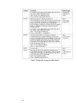
Page 29: ...uration Close restore factory configuration Open Use current configuration CN1 5 Linux Console activation This jumper is used for activating the LINUX Console of the device When the jumper is closed and the device is restarted the use of the console is enabled The activation of LINUX console may be required only for deep debug purpose don t change this jumper if it is not specifically required fro...

Page 30: ...ard as specified in Table 6 Jumper Function Default state JP1 LON net 51 Ohm termination Close JP4 MIP Flash U7 write protect Open Note Close only in case of MIP firmware update Switch Function Note SW1 LON MIP service PIN Use only in case of MIP Firmware update Table 6 Configuration of Jumpers on TS2 Lonwork Xboard TS2 LonWorks Xboard diagnostic and MIP LEDs There are six diagnostic LEDs on the T...

Page 31: ...alid only if the TS2 application is running ON communication failure OFF communication OK OFF DL3 red Data Base Failure The status of this LED is valid only if the TS2 application is running ON DB not present OFF DB present OFF DL4 yellow LON MIP service LED OFF working Steady On Neuron Chip without application and not configured Blinking 0 5Hz Neuron Chip in application status present but not con...

Page 32: ...witched off External tampers connection The two connectors J1 and J3 present on TS2 LonWorks Xboard are designed to connect up to two external tampers for the device not provided Such tampers could be used as anti removal tamper for the device and to connect the anti open tamper of an external case who hosts the TS2 device From factory and when external tampers are not used J1 and J3 are closed wi...

Page 33: ...Tampers If you need to connect an external tamper to the connector J3 you can use the below schematic Figure 20 Single external tamper connection schema Please note that J1 and J3 and so the two external tampers are in series and thus it is not possible to distinguish which of the two tampers raised the alarm From the supervision center the two tampers generate the same events ...

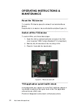
Page 34: ...steps 1 Open the unit by unscrewing the two screws on the front cover requires TORX Tamper Resistant T10 screwdriver 2 Remove the J1 connector of the incoming 12Vcc 3 Press for 3 seconds the reset button Figure 21 TS2 device switch off TS2 application quick health check Using diagnostic Led present on to the TS2 LonWorks Xboard it is possible to perform a first quick check of the TS2 application w...

Page 35: ...ce using Reset button If DL1 ON the device is running the test application Move the device from manufacturing test to FW application closing CN1 7 Data Base present DL6 ON DL2 OFF DL3 OFF If DL3 ON no application DB on the device Check if the supervision centre is up and running Check if the TS2 device is properly configured into EBI If DL2 ON Communication failure with the supervision centre Chec...

Page 36: ...15 UL Omega wired 2 Replace the cable 3 Verify if the battery wires are connected with the right polarity TS2 Battery replacement The battery has to be replaced every 3 years There is no need to check the status of the battery as it is automatically checked by the software application To replace the battery follow these steps see Figure 23 1 Switch the unit OFF 2 Unscrew the two special lateral sc...

Page 37: ...upervised in case of Not presence Low capacity Protection fuse blowout CAUTION Risk of explosion if the battery is connected in the reversed polarity Batteries must be recycled Disposal of used batteries must be in accordance with local environmental regulations ...

Page 38: ...e battery cable will be burned 12VDC connected in reverse way The protection inside the TS2 will avoid permanently damage LON connected on the 12Vcc The protection inside the TS2 will avoid permanently damage the communication with other device will be affected 12VDC connected on the LON The protection inside the TS2 will avoid permanently damage the communication with other device will be effecte...

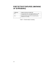
Page 39: ... features and warning TS2 To reduce the fire risk do not operate the device over the operating temperature use specified battery and fuse TS2 To reduce the electric shock risk do not wire the device during power on condition Table 11 Protective features and warning ...

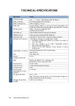
Page 40: ...onnection 10 100 BaseT standard unshielded cable on RJ45 Auto MDIX automatically detects and corrects for straight or cross over cables Error free operation up to 150mt dependable network performance over long distance Superior 4 0 KV ESD protection robust operation in Harsh environments LONWORKS connection Unshielded twisted pair cable in free topology MIP FT3150 Physical Size 221x305x47 mm Weigh...

Page 41: ...tive 2011 65 EU Standards EN 55032 2012 AC 2013 EN 50130 4 2011 A1 2014 EN 60950 1 2006 A11 2009 A1 2010 A12 2011 A2 2013 EN 50581 2012 Access Control System for use in Security Applications Compliance Company name Honeywell S r l Via Philips 12 20052 Monza Italy Product name TS2 Product models TS2 TS2_AC TS2 NE TS2 UL Are in conformity with the following harmonized standard s and other normative ...

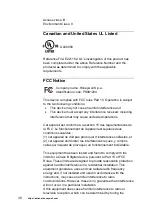
Page 42: ...tionnement de l appareil est sujetaux deux conditions suivantes 1 cet appareil ne doit pas provoquer d interférences néfastes et 2 cet appareil doit tolérer les interférences reçues y compris celles qui risquent de provoquer un fonctionnement indésirable This equipment has been tested and found to comply with the limits for a Class B digital device pursuant to Part 15 of FCC Rules These limits are...

Page 43: ...iant with the European Parliament and Council Directive on the restriction on the use of certain Hazardous Substances in electrical and electronic equipment devices 2011 65 EU WEEE compliance In accordance with directive 2012 19 EU regarding waste electrical and electronic apparatus WEEE effective since 14 February 2014 Honeywell commits when requested by the customer to the collection treatment r...

Page 44: ...40 https extranet honeywell com environmental protection use period 15 years and needs to enter into the recycling system when this period is over ...

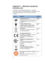
Page 45: ...t package are fragile and the package shall be handled with care Carton Box This way up To indicate correct upright position of the transport package Carton Box Conformité Européenne To indicate the manufacturer declares that the product meets the requirements of the applicable EC directives Label Canadian and United States UL Listed To indicate that the product meets the requirements of the UL609...

Page 46: ...42 https extranet honeywell com ...

Reviews: