Rev. (a)
Ignition Control
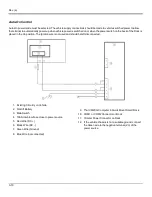
Ignition wire must be connected and the Ignition Control power mode must be selected. When switched vehicle power is
available the Thor VM2CG ignition signal wire can be connected (less than 1mA over input voltage range) to the switched
circuit to allow the Thor VM2CG to power on when the vehicle is switched on. When the vehicle is switched off, more
aggressive power management settings are enabled to preserve the vehicle battery charge.
1. Existing Circuitry on Vehicle
2. Forklift Battery
3. Main Switch
4. 10A Slow blow Fuse close to power source
5. Ignition
6. Red Wire (DC +)
7. Black Wire (DC -)
8. Green Wire (Ground)
9. Blue Wire (Ignition Signal)
10. Thor VM2CG Computer in Quick Mount Smart Dock
11. COM1 or COM2 Connector on Dock
12. Circular Power Connector on Dock
13. If the vehicle chassis is not a suitable ground, connect
the Green wire to the negative terminal (-Vo) of the
power source.
3-9
Summary of Contents for Thor VM2C02
Page 6: ...Rev 01 iv ...
Page 8: ...Rev a Components Front View 1 Power Button 2 Speakers 3 Microphone 1 2 ...
Page 38: ...Rev 01 2 26 ...
Page 58: ...Rev 01 3 20 ...
Page 66: ...Rev 01 4 8 ...
Page 69: ...Rev a 5 3 ...


