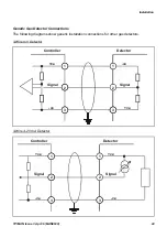
Installation
TP1MAN Issue 3 Apr 06 (MAN0630)
15
Always use suitable wiring techniques and crimps when terminating cable cores, especially if
running two cores to a single terminal.
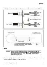
Signal and DC power connections are made via a
16-wire
terminal block. Mains power is
connected via a separate
3-wire
terminal block.
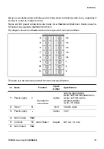
The diagram shows the
16-wire
terminal block layout with terminal identifiers.
This table lists the terminals and their functions and specifications.
Id.
Name
Function
Input/
Output
Specification
1
Power supply
+
Gas detector
connections
Output
4-20 mA input module:
2-wire, 4-20 mA loop powered, or,
3-wire, 4-20 mA source
mV input module:
3-wire, mV bridge
2
Signal
S
Input
Variable signal
3
Power supply
-
Output
0 Vdc
4
N/O Contact
1NO
Alarm Relay 1
Outputs
240 Vac, 3 A max.
5
Common
1C
6
N/C Contact
1NC
A
1 1NO
7 DC+
2 1C
3 1N/C
4 FNO
5 FC
6 FNC
8 DC–
B
2NO
2C
2NC
I+
I–
+
S
--
4
5
6
7
8
9
10
11
12
13
14
15
16
1
2
3


