Installation
TP1MAN Issue 3 Apr 06 (MAN0630)
11
Mounting
Touchpoint 1
is supplied with a mounting bracket that fits onto a suitable wall. The controller is then
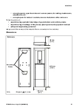
hooked onto the bracket. The previous diagrams show dimensions for
Touchpoint 1
and the bracket.
Fit the bracket to a flat, firm surface, e.g. wall, suitable for the controller’s size and weight.
Recommended screw for mounting is M3.5 x 25 (or #8 x 1").
1
Mark out and drill 4 x M3 holes for the mounting bracket fixing screws.
Use the mounting bracket as a template for the position of the holes.
2
Fix the bracket securely to the wall.
Use appropriate fixings for the surface to which the bracket/controller is mounted.
3
With the bracket secure, locate and then lower Touchpoint 1 onto it.
Ensure both top and bottom hooks on the back of the unit engage properly in the mounting
bracket slots.
12.0 mm
(0.5”)
228.0 mm
(9.0”)
198.0 mm
(7.8”)
240.0 mm
(9.5”)
78.0 mm
(3.0”)
100.0 mm
(3.9”)
Mounting Hole (6 off)
Note
Diagram not to scale.
Thickness - 5.25 mm (0.2”) max.
Mounting
Bracket

