Operation
TP1MAN Issue 3 Apr 06 (MAN0630)
26
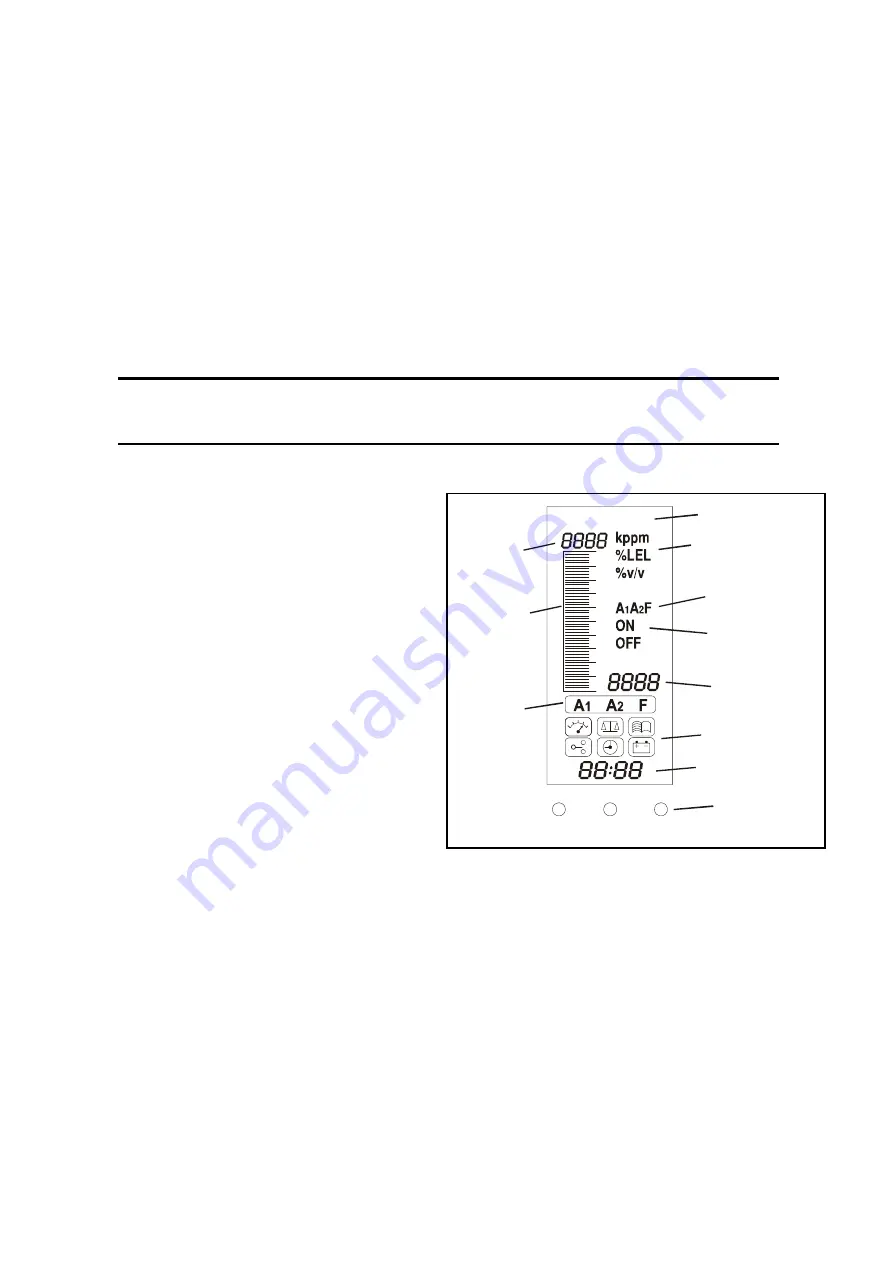
Information on the Display
The controller features a user interface that, during normal operation, displays gas reading
information, and also system fault and information messages.
It displays status and configuration information about the system via a menu options accessed
and controlled via four buttons (3 are hidden) below the display, see
An audible alarm sounds whenever an abnormal event occurs, e.g. gas alarm, fault, etc.
3 LEDs below the screen indicate status information - power on (green), gas alarm (red) and fault
(amber).
Caution
Gas events occurring at the detector while in menu mode are not
reported at the controller.
At switch on all display icons/text/numbers/
symbols on the display are lit for
1 second
.
They then show a warm-up count down from
C180
(
3
minutes) to
C000
.
To skip the warm-up sequence press the
channel’s
Cancel
button for
3
seconds.
The display screen shows the gas
concentration (both graphically and
numerically), range, units, alarm/fault status
and configuration mode.
The diagram shows the display layout.
The meaning of the menu icons is explained
on
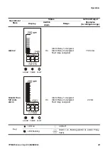
Status Indications
Typical display indications and default relay
status for a particular operational state are
shown in the following examples.
Gas Reading/
Value
Units
Bar Graph
Range
ALARM
POWER
FAULT
Time/Date
Status LEDs
Alarm/Fault
Status
History Records
Power On History
Record/Relay Act
and Reset
Menu Icons
LCD


