Commissioning
TP1MAN Issue 3 Apr 06 (MAN0630)
37
3-wire 4-20 mA Source
This covers connection to gas detectors such as
Sensepoint Plus
and
Sensepoint Pro
.
1
Set up the gas detector.
Refer to the detector’s user manual for details describing how to set up the detector.
2
Check that all power and electrical connections to the controller, and electrical
connections to the gas detector are correct.
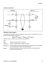
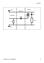
For gas detector access see its user manual. For detector to controller wiring details see
page 20 and page 21.
3
Follow step 2 on page 35.
4
Check for a minimum voltage of 12 Vdc at the gas detector.
See the gas detector user manual. For detectors other than Sensepoint Plus and
Sensepoint Pro refer to their operating instructions.
5
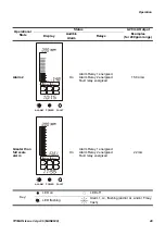
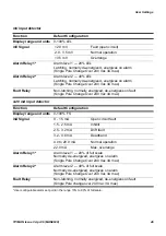
Check that the controller’s display shows the correct gas units and range for the
detector in use.
If not follow the procedure on page 38 to change the gas units and range.
6

