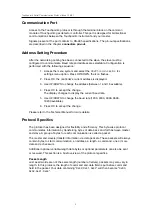
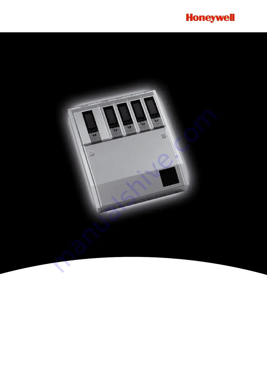
background image

Touchpoint 4 Serial Communication Protocol Issue 1 09/07

Touchpoint 4

Serial Communication Protocol

Summary of Contents for Touchpoint 4

Page 1: ...Touchpoint 4 Serial Communication Protocol Issue 1 09 07 Touchpoint 4 Serial Communication Protocol ...

Page 2: ...Command 6 Data 7 Checksum 7 GENERIC DATA FORMATS 7 Date Format 7 Time Format 7 Date Time Examples 7 Concentration Code 7 Concentration Data Format Code 8 Concentration Example 8 GENERIC RESPONSES 8 ACK 0x01 8 NAK 0x21 9 Bad Packet 0x66 9 Unknown CMD 0x67 9 PROTOCOL COMMAND DEFINITION 9 HANDSHAKE COMMAND 0X40 9 Command packet to instrument 9 Example 9 Response packet from instrument 9 Example 9 GET...

Page 3: ...M 0X41 12 Command packet to instrument 12 Example 12 Response packet from instrument 13 Example 13 PHYSICAL LAYER 13 PREAMBLE 13 ELECTRICAL INTERFACES 13 Multipoint Serial Bus Infrastructure 13 Multipoint System requirements 14 MECHANICAL INTERFACES 15 Connectors pin out 15 ...

Page 4: ...5 serial communications This configuration requires a master device Therefore one Touchpoint 4 gas detector controller will not communicate directly with another Touchpoint 4 gas detector controller However one master can be used to communicate with more than one Touchpoint4 gas detector controllers on a two wire RS 485 bus The Touchpoint 4 gas detector controller supports multiple baud rates Thes...

Page 5: ... to the Touchpoint4 gas detector controller Master A computer or PLC that communicates with slaves using the Touchpoint4 protocol Packet A block of information that is passed between the master and the slave A packet is made from many bytes of information Protocol The manner in which data is transferred and the format used for the transfer Touchpoint4 protocol refers to the packets of transferred ...

Page 6: ...OK to accept the change The display changes to display the current baud rate 5 Use UP DOWN to change the baud rate 1200 2400 4800 9600 19200 available 6 Press OK to accept the change Please refer to the Technical Manual for more details Protocol Specifics The protocol has been designed for flexibility and efficiency This byte wise protocol communicates information by transferring bytes of data bac...

Page 7: ...invalid address an invalid length byte or an invalid checksum Otherwise the probability of an evacuation because of simple network noise is unnecessarily large The actual data in the packet is interpreted in a somewhat different manner from our previous examples Both the master and the slave communicate using the packet format in Figure 2 It contains a start code an address a length a command and ...

Page 8: ...as detector controller address 0X01 to 0X10 1 to 16 decimal Length Size 1 byte The number of bytes in the Command field and Data field The total packet length is 4 bytes larger than this Command Size 1 byte This is 0x30 0x40 or 0x41 as defined in the remainder of this book Data Size 0 250 byte s This section varies according to the chosen command and may be omitted Checksum Size 1 byte The bit wis...

Page 9: ...9 would be 1989 1980 9 Time Format 2 bytes Bit 15 11 10 5 4 0 Year Month Day Figure 4 Time format Hours 5 bits Minutes 6 bits Seconds 5 bits Seconds always be 0 Date Time Examples Date 1F 56 Oct 22 1995 Date 1F 75 Nov 21 1995 Time 13 C0 02 30 00 Time 74 00 14 32 00 Time 47 00 08 56 00 Concentration Code 2 bytes Bit 15 8 7 0 H L Figure 5 Concentration code format For example HEX 013D represents the...

Page 10: ... 9 8 V V 0100 0000 40 98 LEL Generic Responses There are four generic responses Each of these response packets is 6 bytes and contains the start byte address length command code ACK NAK code and Checksum All ACK NAK code is sent following the command code in the last received packet ACK 0x01 This is used for an acknowledgement of the handshake command NAK 0x21 This is used for a negative acknowled...

Page 11: ... 0x40 ACK code 0x01 Checksum 1 byte Example The addressed 01 instrument receives the handshake command and responses 0x7f 0x01 0x02 0x40 0x01 0x3d Get unit and points status 0x30 This command requests the instrument date time alarm status fault status and up to four channel s status Command packet to instrument Command code 0x30 Data field null Checksum 1 byte Example 0x7f 0x01 0x01 0x30 0x4f mean...

Page 12: ... bytes so the length field of the response packet depends on the quantity of the channel of Touchpoint4 For example if there are 4 channels the length will be 1 Command 6 Data Time Unit alarm status Unit fault status 6 bytes per channel 4 channels 31 If there are 2 channels the length will be 1 6 6 2 19 Note that once instrument receives the Get unit and points status command it always send out al...

Page 13: ...cted Channel 2 and Channel 4 Example 3 0x7f 0x01 0x1f 0x30 0x1f 0x56 date OCT 22 1995 0x13 0xc0 time 02 30 00 0x01 alarm A1 alarm 0x00 fault no fault 0x01 channel number 1 0x81 0x00 0x62 concentration 9 8 V V 0x01 alarm A1 alarm 0x00 fault no fault 0x02 channel number 2 0x81 0x00 0x62 concentration 9 8 V V 0x01 alarm A1 alarm 0x00 fault no fault 0x03 channel number 3 0x81 0x00 0x62 concentration 9...

Page 14: ...m or fault Command packet to instrument Command code 0x41 Data field null Example If the master wants to reset latched outputs of addressed 01 instrument it should send out 0x7f 0x01 0x01 0x41 0x3e Response packet from instrument Command code 0x41 Data field null Example The addressed 01 instrument receives the reset fault alarm command and responses 0x7f 0x01 0x01 0x41 0x3e 11 ...

Page 15: ...or transmitting The following figure gives a general overview of the serial bus infrastructure in Touchpoint4 Serial Communication system Figure 6 Communication infrastructure The Touchpoint4 gas detector controllers are connected directly to the trunk cable The master PC or PLC is connected directly or via a derivation according to the master instruction The cable should be shielded Note the Touc...

Page 16: ...e short never more than 20m Grounding Arrangements At one end of each cable its shield must be connected to protective ground Line Termination To minimize the reflections from the end of the RS485 cable it is recommended to place a Line Termination near each of the 2 Ends of the Bus It is important that the line must be terminated at both ends since the propagation is bi directional but it is not ...

Page 17: ...ommunication Protocol Issue 1 09 07 Mechanical Interfaces Connectors pin out The following figure shows the pin out on the terminal block of Touchpoint4 gas detector controller Figure 7 Touchpoint4 communication pin out 14 ...

Page 18: ...3 4300 Fax 41 0 44 943 4398 gasdetection honeywell com Americas Honeywell Analytics Distribution Inc 400 Sawgrass Corporate Pkwy Suite 230 Sunrise FL 33325 USA Tel 1 954 514 2700 Toll free 1 800 538 0363 Fax 1 954 514 2784 detectgas honeywell com www honeywell com Technical Services ha global service honeywell com Asia Pacific Honeywell Analytics Asia Pacific 508 Kolon Science Valley 1 187 10 Guro...

Reviews: