4
TP970 AND TP9600 SERIES PNEUMATIC THERMOSTATS
77-9382—1
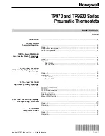
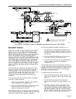
Figure 5 shows the valve unit bleeding down the BLP. This
condition occurs when the bimetal sensing element relaxes
its force against the flapper, allowing the nozzle-flapper gap
to increase.
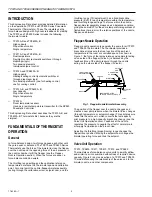
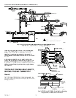
Fig. 6. Basic TP973 and TP9630 Thermostat.
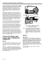
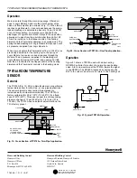
The TP973 and TP9630 are used on one- or two-pipe
systems. Connections are made to main and branch for two-
pipe applications (see Fig. 7). The main air connector is
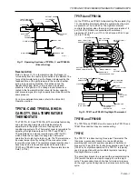
plugged when used on one-pipe applications (Fig. 8). This
causes the Thermostat to operate like any other bleed-type
thermostat with a remote restrictor.
Fig. 5. Valve Unit Shown with Pilot
Chamber Pressure Decrease.
The reduction in pilot pressure against the pilot diaphragm
allows the BLP to overcome the pressure in the pilot
chamber. This change moves the valve piston down, sealing
off Point B and opening Point A. Branchline air bleeds off
until the pressure against the branchline diaphragm equals
the pressure against the pilot chamber diaphragm. When the
pressures become equal, the exhaust air is shut off at Point
A. The valve unit is again in a balanced condition at the new
pressure. The arrows in the air passages in Figure 5 show
the direction of airflow.
The preceding explanation of valve unit operation is very
important to understanding TP970, TP9600, TP971, TP9610,
TP972, and TP9620 operation. As can be seen from Figures
3, 4, and 5, pilot pressure changes affect BLP changes in
the same ratio. There is no pressure gain to amplify errors as
with other pneumatic Thermostats. Still, the main air supply
being switched through the valve unit, provides fast, high
capacity increase and decrease of BLP.
TP973A, B AND TP9630 A, B LOW-
CAPACITY, SINGLE-TEMPERATURE
THERMOSTATS
General
The TP973A, B TP9630A, B (Fig. 6) are the simplest
Thermostats in the TP970 and TP9600 Series. Every other
model includes the basic TP973 and TP9630 assembly with
additions. Air going to the controlled device from the TP973
and TP9630 passes through an internal restrictor. The
TP973A and TP9630A are direct acting (signal pressure
increases as the temperature increases); the TP973B,
reverse acting (signal pressure increases as the temperature
decreases).
POINT A
EXHAUST
AIR
VALVE
PISTON
POINT B
MAIN LINE
BRANCH
LINE
PILOT AIR
C6050-1
NOTE: THE SEAL AT POINT A DOES NOT
ALLOW AIR TO EXHAUST.
VALVE
Fig. 7. TP973 and TP9630 Operating Section.
MAIN LINE
TO CONTROLLED
DEVICE
BACKPLATE
BRANCH
LINE
RESTRICTOR
NOZZLE
NOZZLE
CHAMBER
FLAPPER
THROTTLING RANGE
ADJUSTMENT
BIMETAL
CALIBRATION
SCREW
SETPOINT
KNOB
CAM
SLOPE
SETPOINT
CAM
C6052
FLAPPER
THROTTLING
RANGE
ADJUSTMENT
BIMETAL
NOZZLE
CALIBRATION
SCREW
SETPOINT
CAM
SETPOINT
KNOB
SETPOINT
KNOB
AIR CONNECTION
FILTER AND
RESTRICTOR
C6051

