X-XX UL
INSTALLATION INSTRUCTIONS
®U.S. Registered Trademark
Copyright © 1995 Honeywell Inc. • All Rights Reserved
APPLICATION
The C7089 Outdoor Sensor is used with the PC8900
Perfect Climate Comfort Center™ Control System and the
W8900 Remote Module. It senses the outdoor tempera-
ture for display on the PC8900 at the touch of a key. The
sensor is encapsulated to protect against water and
contaminants, and includes 60 in. leadwires.
SPECIFICATIONS
Operating Ambient Temperature Range:
-40 to 128
°
F (-40 to 53
°
C)
Operating Relative Humidity:
5% to 95% noncondensing
Dimensions in inches (millimeters):
2-1/4 (57) x 3/8 (10) with 60 (1524) leadwires
C7089A Outdoor Sensor
INSTALLATION
When Installing this Product…
1
Read these instructions carefully. Failure to follow
them could damage the product or cause a hazard-
ous condition.
2
Check the ratings given in the instructions and on
the product to make sure the product is suitable for
your application.
3
Installer must be a trained, experienced service
technician.
4
After installation is complete, check out product
operation as provided in these instructions.
CAUTION
Disconnect power supply before connecting wiring
to prevent electrical shock or equipment damage.
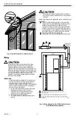
Location and Mounting (Fig. 1)
Mount the sensor where:
• setting can not be tampered with.
• there is good air circulation.
• it can measure the true outdoor ambient
temperature.
• surface is flat.
• the wire distance between the C7089 and W8900 is
less than 200 feet.
Do
not mount the sensor:
• in the direct sunlight.
• where hot or cold air blows on the sensor. Discharge
line from an outdoor compressor unit, vent or fan will
cause inaccurate temperature readings.
• where snow, ice or debris can cover it.
Use the following steps to mount the sensor:
1
Remove the sensor from the mounting clip.
2
Mark the area on the surface where the C7089
mounting clip will be mounted.
3
Mount the clip.
69-0896-1


