background image

H1008A,D AUTOMATIC HUMIDITY CONTROL


69-1185EF  4

2


Location and Mounting 

H1008A,D Automatic Humidity Control 

IMPORTANT


Do not install H1008 on supply air. Temperatures 
in excess of 120°F cause the control to go into 
error mode. If mounting near an elbow area, 
keep the control 6 in. (152 mm) upstream from 
the elbow so the humidity and temperature sen- 
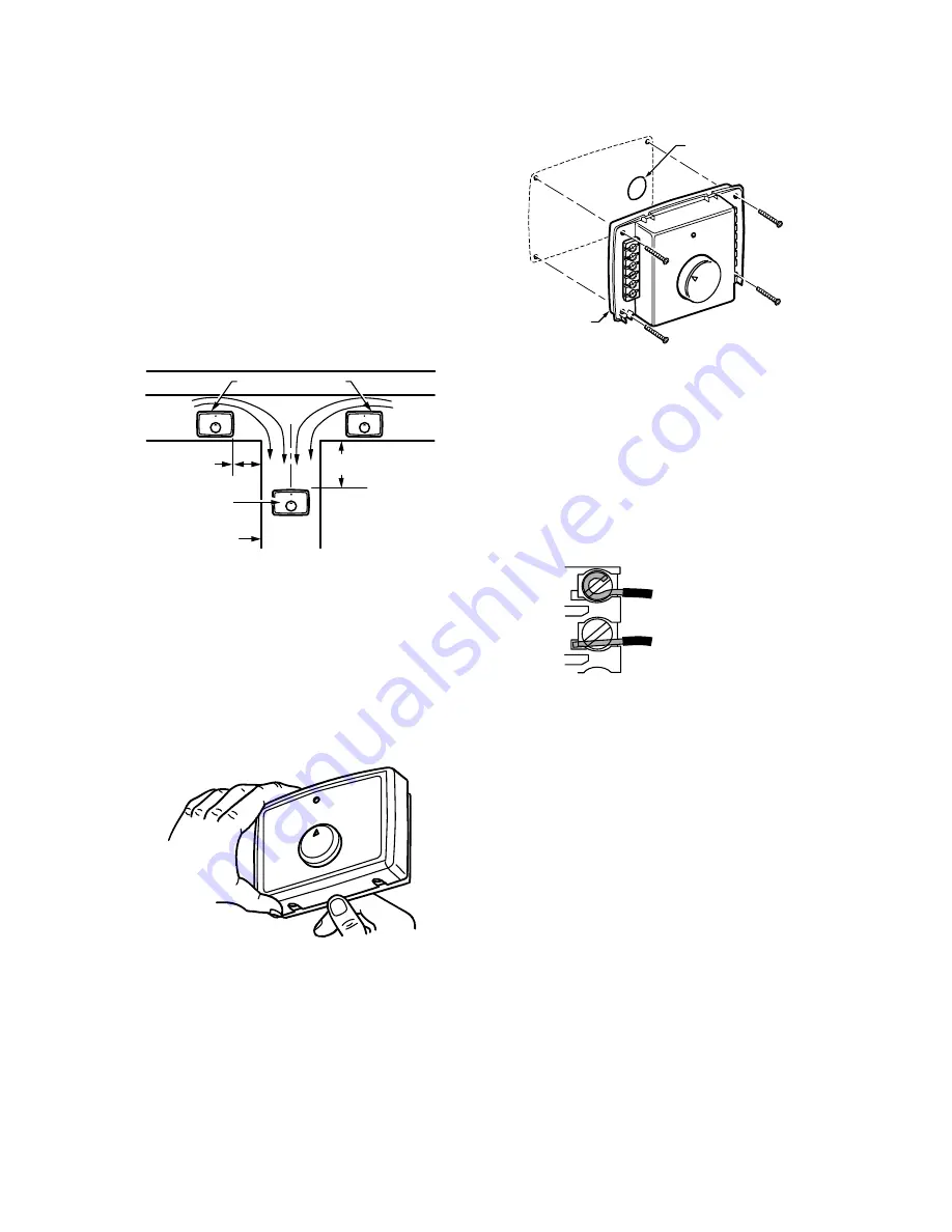
sor is exposed to the normal airflow (Fig.1).


Locate the control at least 12 in. (305 mm) upstream from 
the humidifier (or dehumidifier/ventilator supply air) in the 
return air duct where it can be exposed to the air stream 
of the return air. See Fig. 1.


Fig. 1. Select duct location for control.


Use the following procedure to mount the H1008A,D in 
the return air duct:


1.

  Î

emove the cover by placing your thumb in the bot- 

tom notch between the cover and the base and pull- 
ing out and up. See Fig. 2.


Fig. 2. Remove cover from base. 

2.

  Ü®

ill 3/4 in. (19 mm) circular opening for the projec- 

tion on the back of the base. See Fig. 3. Place the 
device on the duct and mark the mounting holes, or 
screw in self-tapping screws. 

NOTE:

Be sure the sheet metal surface is flat after 
drilling and cutting holes.


Fig. 3. Mount control on return air duct. 

3.

  Mount the base on the duct using the four mounting 

screws provided. Tighten the screws until fully 
seated with no space between the base and the 
duct. See Fig. 3.


4.

  Run a low voltage wire from the humidifier (and 

dehumidifier or ventilator for H1008D) and equip- 
ment to the control terminals. See Fig. 5-9. Use 
either straight in or wraparound wiring connections. 
See Fig. 4.


5.

  Snap the cover onto the base.


Fig. 4. Correct wiring technique.


C7089H Outdoor Temperature Sensor 

NOTE:

The C7089H Outdoor Temperature Sensor is 
recommended when using the control with heat 
pump. 

Mount the sensor (purchased separately): 
 

out of direct sunlight on the North side of the house. 


at least three feet from dryer vents or other vents. 


above the expected snow line where ice and debris 
cannot cover it. 

Use the following procedure for mounting:


1.

  Place the sensor in the clamp provided.


2.

  Insert the screw provided through both of the holes 

in the clamp and fasten the sensor in place.


ßÔÌÛÎÒßÌÛ ÔÑÝßÌ×ÑÒ 

ÎÛÌËÎÒ 
ß×Π

ÎÛÌËÎÒ 
ß×Π

ê ·²ò Åïëî ³³Ã 
Ó×Ò×ÓËÓ 

ïë ·²ò Åíèï ³³Ã 
Ó×Ò×ÓËÓ 

ÞÛÍÌ 
ÔÑÝßÌ×ÑÒ 

ÎÛÌËÎÒ ß×ΠÜËÝÌ 

Óïîèîî 

Óïîèîè 

ÞßÍÛ 

Óïîèîçß 

íñì ×Òò ØÑÔÛ 

Óïîèîé 

ÚÑΠÉÎßÐßÎÑËÒÜ 
×ÒÍÛÎÌ×ÑÒ ÍÌÎ×Р
éñïê ×Òò øïï ÓÓ÷ò 

ÚÑΠÍÌÎß×ÙØÌ 
×ÒÍÛÎÌ×ÑÒ ÍÌÎ×Р
ëñïê ×Òò øè ÓÓ÷ò

Summary of Contents for Tradeline H1008A

Page 1: ...t help balance the moisture content of your indoor air Honeywell is proud to be a partner of the American Lung Association Health House program contributing annually to the Lung Association The Health House program provides guidelines for constructing homes with improved air quality and ventilation For more information on ways to improve the air inside your home please visit the Health House websi...

Page 2: ... is flat after drilling and cutting holes Fig 3 Mount control on return air duct 3 Mount the base on the duct using the four mounting screws provided Tighten the screws until fully seated with no space between the base and the duct See Fig 3 4 Run a low voltage wire from the humidifier and dehumidifier or ventilator for H1008D and equip ment to the control terminals See Fig 5 9 Use either straight...

Page 3: ...t the humidifier to the two HUM terminals on the H1008A D as shown in Fig 5 through 8 3 In furnace systems with two transformers connect CG to the cooling system transformer common and connect CW to the heating transformer common Be sure G and W connect to the R terminals of both transformers If only one transformer is used leave the jumper on CG and CW See Fig 10 4 To wire the C7089H Outdoor Temp...

Page 4: ...ÝÑÒÌÎÑÔò ÚßÒ ÌÛÎÓ ÒßÔÍ Ù ßÒÜ ÝÙ ÒÑÌ ËÍÛÜ Ò ÌØ Í ßÐÐÔ ÝßÌ ÑÒò ÛÈÌÛÎÒßÔ ÌÎßÒÍÚÑÎÓÛÎ ÒÑÌ ÐÎÑÊ ÜÛÜò Ú ÑËÌÜÑÑÎ ÌÛÓÐÛÎßÌËÎÛ ÍÛÒÍÑÎ Í ÒÑÌ ËÍÛÜô É ÎÛ ØÛßÌ ÌÛÎÓ ÒßÔÍ É ßÒÜ ÝÉ ÌÑ ÚËÎÒßÝÛò Ú ËÍ ÒÙ ÑËÌÜÑÑÎ ÌÛÓÐÛÎßÌËÎÛ ÍÛÒÍÑÎô ÎÛÓÑÊÛ ÚßÝÌÑÎÇ ÒÍÌßÔÔÛÜ ÖËÓÐÛÎò î ßËÌÑÓßÌ Ý ØËÓ Ü ÌÇ ÝÑÒÌÎÑÔ Ôï øØÑÌ Óïíîçè Ôî ï í ê ÍÑÔßÌÛÜ ÎÛÔßÇ ÝÑÒÌßÝÌÍò ØÛßÌ ÑÒÔÇ ßÐÐÔ ÝßÌ ÑÒ ÍØÑÉÒò Í Ó ÔßÎ É Î ÒÙ ÎÛÏË ÎÛÜ Ò ØÛßÌ ßÒÜ ÝÑÑÔ ÍÇÍÌÛÓ É...

Page 5: ...ÔÔ Ì ÓÛÍò ÜÑ ÒÑÌ ËÍÛ ÚßÒ ÞÑßÎÜ ØËÓ Ü ÍÌßÌ ÝÑÒÌßÝÌÍ ÑÎ ÝËÎÎÛÒÌ ÍÛÒÍ ÒÙ ÎÛÔßÇò ÝËÌ ÖËÓÐÛÎ ÚÑÎ ÜÛØËÓ Ü Ú ÛÎ ßÐÐÔ ÝßÌ ÑÒò øÜÑ ÒÑÌ ÝËÌ ÚÑÎ ÊÛÒÌ ÔßÌ ÑÒ ÍÇÍÌÛÓò ÜÛØËÓ ÌÛÎÓ ÒßÔÍ ÍÉ ÌÝØ ÔÑÉ ÊÑÔÌßÙÛ ÜÛØËÓ Ü Ú ÛÎÍô ØÛßÌñÛÒÛÎÙÇ ÎÛÝÑÊÛÎÇ ËÒ ÌÍ ÑÎ ÛÈÌÛÎÒßÔ ÝÑÒÌßÝÌÑÎÍ ÌØßÌ ÍÉ ÌÝØ Ø ÙØ ÊÑÔÌßÙÛ ÜÛØËÓ Ü Ú ÛÎÍò ÖËÓÐÛÎ ßÒÜ ÜÛØËÓ ÌÛÎÓ ÒßÔÍ ÒÑÌ ÐÎÛÍÛÒÌ ÑÒ Øïððèß ÓÑÜÛÔò ë ÎÑÑÓ ÌØÛÎÓÑÍÌßÌ é Ôï øØÑÌ Ôî ï Î É Ù ÚßÒ ÎÛÔßÇ Ø...

Page 6: ...re is inferred without the need for an outdoor sensor or measured with optional outdoor sensor by the HumidiCalc Software Indoor humidity and temperature information is measured by sensors located on the back of the control The frost factor set by using the frost factor dial allows for variables in furnace oversizing window insulation and average daily outdoor temperature The Automatic Humidity Co...

Page 7: ...ture drops Table 4 shows approximate sensor resistance values at various temperatures Test Mode Use the following procedure to place the control in the test mode and call for humidification dehumidification 1 Ìurn the frost factor setpoint dial to the Test position 2 Do one of the following a At the thermostat with the system switch set to Heat and the fan switch to Auto move the tem perature setp...

Page 8: ...ns Honeywell International Inc Honeywell Limited Honeywell Limitée 1985 Douglas Drive North 35 Dynamic Drive Golden Valley MN 55422 Toronto Ontario M1V 4Z9 http yourhome honeywell com U S Registered Trademark 2006 Honeywell International Inc 69 1185EF 4 M S Rev 07 06 ...

Page 9: ...s chacune des parties de la maison ou d humidificateurs ou de thermostats évolués qui aident à équilibrer le taux d humidité de l air ambiant Honeywell est fière de s associer au programme Health House de l association pulmonaire américaine American Lung Association et de verser un don annuel à l association Le programe Health House donne des directives sur la construction de maisons saines où la ...

Page 10: ... ser les vis autotaraudeuses REMARQUE S assurer que la surface de tôle est bien plate après avoir percé les ouvertures Fig 3 Installation du régulateur dans la gaine de reprise 3 Fixer le boîtier à la gaine à l aide des quatre vis de fixation fournies Serrer les vis fermement jusqu à ce qu il n y ait plus d espace entre le boîtier et la gaine Voir la Fig 3 4 Faire passer un fil basse tension de l ...

Page 11: ...eux bornes HUM des H1008A D comme l illustrent les Fig 6 à 10 3 Dans les systèmes de chauffage à deux transfor mateurs raccorder CG au commun du transforma teur du système de refroidissement et raccorder CW au commun du transformateur de chauffage Il faut s assurer que G et W sont raccordés aux bornes R des deux transformateurs s il n y a qu un transformateur il faut laisser le cavalier entre CG e...

Page 12: ...Íò ÌÎßÒÍÚÑÎÓßÌÛËÎ ÑÐÌ ÑÒÒÛÔ ÒÑÒ ÚÑËÎÒ ò Í ÔÛ ÝßÐÌÛËÎ ÜÛ ÌÛÓÐ ÎßÌËÎÛ ÛÈÌ Î ÛËÎÛ ÒKÛÍÌ ÐßÍ ËÌ Ô Í ô ÎßÝÝÑÎÜÛÎ ÔÛÍ ÞÑÎÒÛÍ ÜÛ ÝØßËÚÚßÙÛ É ÛÌ ÝÉ U ÔKßÐÐßÎÛ Ô ÜÛ ÝØßËÚÚßÙÛò Í ËÒ ÝßÐÌÛËÎ ÜÛ ÌÛÓÐ ÎßÌËÎÛ ÛÈÌ Î ÛËÎÛ ÛÍÌ ËÌ Ô Í ô ÎÛÌ ÎÛÎ ÔÛ ÝßÊßÔ ÛÎ ÒÍÌßÔÔ ÛÒ ËÍ ÒÛò î ØÇÙÎÑÍÌßÌ ßËÌÑÓßÌ ÏËÛ Ôï øÍÑËÍ ÌÛÒÍ ÑÒ ÓÚïíîçè Ôî ï í ê ÝÑÒÌßÝÌÍ ÜË ÎÛÔß Í ÜK ÍÑÔßÌ ÑÒ ÍÇÍÌ7ÓÛ ÜÛ ÝØßËÚÚßÙÛ ÍÛËÔÛÓÛÒÌ ÔÔËÍÌÎ ò ÎßÝÝÑÎÜÛÓÛÒÌ Í ...

Page 13: ... ÔßÌÛËÎ ÜÛ ÔKØËÓ Ü ÍÌßÌ ÑË ÔÛ ÎÛÔß Í ÝßÐÌÛËÎ ÜÛ ÝÑËÎßÒÌò ÝÑËÐÛÎ ÔÛ ÝßÊßÔ ÛÎ ÐÑËÎ ÔÛÍ ßÐÐÔ ÝßÌ ÑÒÍ ßÊÛÝ Ü ÍØËÓ Ü Ú ÝßÌÛËÎ øÒÛ ÐßÍ ÝÑËÐÛÎ ÔÛ ÝßÊßÔ ÛÎ ÐÑËÎ ÔÛ ÍÇÍÌ7ÓÛ ÜÛ ÊÛÒÌ ÔßÌ ÑÒ ò ÞÑÎÒÛÍ ÜË Ü ÍØËÓ Ü Ú ÝßÌÛËÎ ÏË ÓÛÌÌÛÒÌ ÍÑËÍ ÌÛÒÍ ÑÒ ÔÛÍ Ü ÍØËÓ Ü ÚÝßÌÛËÎÍ ÞßÍÍÛ ÌÛÒÍ ÑÒô ÔÛÍ ßÐÐßÎÛ ÔÍ ÜÛ Î ÝËÐ ÎßÌ ÑÒ ÜK ÒÛÎÙ Û ÛÌ ÜÛ ÝØßÔÛËÎ ÑË ÝÑÒÌßÝÌÛËÎÍ ÏË ÓÛÌÌÛÒÌ ÍÑËÍ ÌÛÒÍ ÑÒ ÔÛÍ Ü ÍØËÓ Ü ÚÝßÌÛËÎÍ ØßËÌÛ ÌÛÒÍ ÑÒò ...

Page 14: ...st calculée par déduction il n est donc pas nécessaire d installer un capteur de température extérieure ou mesurée avec un capteur de température extérieure en option par le logiciel HumidiCalc MC Le H1008D met le ventilateur ou le déshumidificateur en marche pour abaisser le taux d humidité intérieure lorsque le point de rosée de la maison dépasse 58 F Les données sur la température et l humidité...

Page 15: ...puis plus de 24 heures ou encore si le capteur de température extérieure indique plus de 17 C le régulateur est alors en mode d arrêt automatique Le régulateur fonctionnera seule ment si le système de chauffage est sous tension ou encore lorsque la température extérieure est sous 16 C afin d empêcher le climatiseur et l humidificateur de fonctionner simultanément Le régulateur peut passer au mode ...

Page 16: ...mande de chaleur ou b Mettre le sélecteur du système à Off et le sélecteur du ventilateur à On pour que le venti lateur fonctionne en continu 3 Êérifier l humidificateur et ou le déshumidifica teur le ventilateur est en marche Lorsque l hygrostat est en mode d essai le voyant reste allumé quatre secondes puis s éteint quatre secondes Le voyant clignote tant que l hygrostat est en mode d essai Aprè...

Reviews: