Q314 and Q327A
Pilot Burners
J. H. • Rev. 12-92 • © Honeywell Inc. 1992 • Form Number 69-0519—3
TRADELINE
Application
Pilot burners provide main burner ignition for standing pilot natural and LP gas systems. Used with a thermocouple to provide
automatic pilot safety control. Used with a thermopile in a self-powered system. See Table 1 for model specifications.
TABLE 1—MODEL SPECIFICATIONS.
Primary
Type of
Pilot Tip
Model
Aerated
Orifice
Type
Includes
Q314A
No
Insert
Target
Includes natural and LP gas orifices, 1/4 in.
compression fitting, “F,” “K,” or “L” tip styles,
“B” mounting bracket, and “A” mounting bracket
adapter.
Q327A
Yes
Spud
Target
Includes natural and LP gas orifices, 1/4 in.
compression fitting, and “B” mounting bracket
with screws.
Installation
WHEN INSTALLING THIS PRODUCT…
1. Read these instructions carefully. Failure to follow
instructions can damage product or cause a hazardous condi-
tion.
2. Check ratings given in instructions and on product to
make sure product is suitable for your application.
3. Make sure installer is a trained, experienced service
technician.
4. After completing installation, use these instructions to
check out product operation.
WARNING
FIRE OR EXPLOSION HAZARD
CAN CAUSE PROPERTY DAMAGE,
SEVERE INJURY, OR DEATH
Follow these warnings exactly.
1. Disconnect power supply before wiring to pre-
vent electrical shock or equipment damage.
2. To avoid dangerous accumulation of fuel gas,
turn off gas supply at appliance service valve
before starting installation and perform Gas
Leak Test after completion of installation.
3. Do not bend pilot tubing at the control or pilot
after compression nut has been tightened. Gas
leakage at the connection may result.
Follow appliance manufacturer’s instructions if avail-
able; otherwise, use instructions provided below.
LOCATION
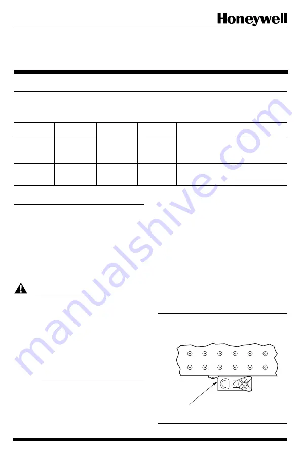
1. Position pilot burner for easy access, observation, and
lighting. In replacement applications, replace pilot burner
with an identical unit and position new pilot burner in the
same location and orientation as the original pilot burner.
2. Mount pilot burner on main burner. Mounting surfaces
other than the main burner can shift, bend, or warp as furnace
expands and contracts while operating. See Fig. 1.
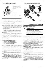
3. Mount pilot burner so the ignition flame remains
properly positioned with respect to the main burner flame.
See Fig. 2.
4. Supply pilot flame with ample air free of combustion
products.
5. Do not impinge pilot flame on adjacent parts. Do not
impinge main burner flame on pilot burner.
6. Do not expose pilot flame to falling scale which could
impair ignition of main burner.
7. Do not expose pilot burner to main burner rollout while
igniting or extinguishing.
8. Do not expose pilot flame to drafts that push or pull
pilot flame away from the thermocouple or thermopile.
Fig. 1—Mount pilot burner on main burner.
PILOT
BURNER/GENERATOR
MUST BE RIGIDLY
POSITIONED
RELATIVE TO
MAIN BURNER
M1263
Summary of Contents for TRADELINE Q314
Page 6: ...6 ...
Page 7: ...7 69 0519 3 ...


