SV9501/SV9502/SV9601/SV9602 SMARTVALVE
TM
SYSTEM CONTROL
11
69-1270—3
NOTE: The SV9502 and SV9602 have an
approximately 30-second prepurge delay before
start of Ignition Trial. Be sure to wait for prepurge
to be completed.
Turning the Appliance OFF
Vacation Shutdown
Set the thermostat to the desired temperature while you
are away.
Complete Shutdown
1.
Turn off the power to the appliance.
2.
Move the ignition system control switch to OFF
without forcing it.
The appliance shuts off completely.
Follow the instructions in Instructions to the Homeowner
to resume normal operation.
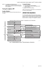
OPERATING SEQUENCE
The following flowcharts describes the basic operating
sequence for the SV9500 and SV9501/SV9502/SV9602/
SV9601 controls. This information is designed to assist
field technicians to analyze normal appliance operation.
Fig. 13. SV9500/SV9600 SmartValve
TM
System Sequence of Operation.
APPLY 24V POWER TO SYSTEM
START
THERMOSTAT CALLS FOR HEAT
A POWERED PILOT VALVE OPENS AND IGNITER
ENERGIZES
PILOT LIGHTS, FLAME ROD SENSES FLAME
• IGNITER OFF
• MAIN VALVE OPENS
• MAIN BURNER LIGHTS
• ELECTRONIC FAN TIMER OUTPUT ENERGIZES
THERMOSTAT CALL FOR HEAT ENDS
• MAIN AND PILOT VALVES CLOSE
• ELECTRONIC FAN TIMER OUTPUT DE-ENERGIZES
NO SYSTEM RESPONSE—PILOT VALVE OFF
NO
IGNITER STAYS ON, PILOT VALVE REMAINS OPEN
MAIN VALVE CLOSES
SV9500 POWERS IGNITER CIRCUIT
IGNITION
MAIN BURNER
OPERATION
END
SV9500/SV9600 SmartValve® FAMILY SEQUENCE OF OPERATION
PILOT AND MAIN VALVES CLOSE, SYSTEM SHUTS DOWN
FLAME SIGNAL DETECTED
• WAIT FOR FLAME SIGNAL TO DISAPPEAR
• ELECTRONIC FAN TIMER OUTPUT ENERGIZES
• PILOT VALVE AND IGNITER REMAIN OFF
SELF-CHECK
NO
M17145B
YES
YES
IGNITER
MISSING
OR
BROKEN
FLAME
OUTAGE
OCCURS
DURING
RUN CYCLE
IGNITER
OPENS
YES
NO


