SV9501/SV9502/SV9601/SV9602 SMARTVALVE
TM
SYSTEM CONTROL
69-1270—3
4
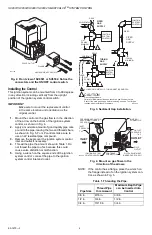
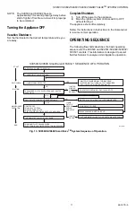
Fig. 2. Front view of SV9501 or SV9502. Notice the
connectors and the ON/OFF control switch.
Installing the Control
This ignition system can be mounted from 0 to 90 degrees
in any direction including vertically from the upright
position of the ignition system control switch.
IMPORTANT
Make sure to mount the replacement control
in the same location and orientation as the
original control.
1.
Mount the control so the gas flow is in the direction
of the arrow on the bottom of the ignition system
control, as shown in Fig. 4.
2.
Apply a moderate amount of good quality pipe com-
pound to the pipe, leaving the two end threads bare,
as shown in Fig. 5. For LP controls make sure to
use an LP resistant pipe compound.
3.
Remove the seals over the ignition system control
inlet and outlet if necessary.
4.
Thread the pipe the amount shown in Table 1. Do
not thread the pipe too far, because this could
cause valve distortion or malfunction.
5.
Using a wrench on the square ends of the ignition
system control, connect the pipe to the ignition
system control inlet and outlet.
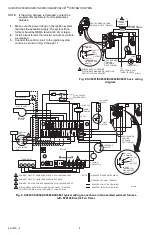
Fig. 3. Sediment trap installation.
Fig. 4. Mount so gas flows in the
direction of the arrows.
NOTE: If the control has a flange, place the wrench on
the flange instead of on the ignition system con-
trol, as shown in Fig. 6.
Table 1. Threading the Pipe.
M17142
VALVE OUTLET
FLANGE
9/64 INCH HEX SCREWS (4)
Pipe Size
Thread Pipe
this Amount
Maximum Depth Pipe
can be Inserted into
Control
3/8 in.
9/16 in.
3/8 in.
1/2 in.
3/4 in.
1/2 in.
3/4 in.
13/16 in.
3/4 in.
HORIZONTAL
DROP
PIPED
GAS
SUPPLY
PIPED
GAS
SUPPLY
3 IN.
(76 MM)
MINIMUM
3 IN.
(76 MM)
MINIMUM
RISER
IGNITION
SYSTEM
CONTROL
TUBING
GAS
SUPPLY
HORIZONTAL
DROP
3 IN.
(76 MM)
MINIMUM
RISER
M3343C
1
IGNITION
SYSTEM
CONTROL
IGNITION
SYSTEM
CONTROL
1
CAUTION
Gas Leakage Hazard.
Failure to follow precautions can result in a gas-filled work area.
Shut off the main gas supply before removing end cap. Test for gas
leakage when installation is complete.
ALL BENDS IN METALLIC TUBING MUST BE SMOOTH.
CONTROL
IGNITER
OFF
ON
OUTLET
PRESSURE
TAP
PRESSURE REGULATOR
ADJUSTMENT (UNDER
CAP SCREW
)
INLET
PRESSURE
TAP
INLET
IGNITION SYSTEM
CONTROL SWITCH
IGNITER
CONNECTOR
PILOT
OUTLET
PILOT ADJUSTMENT
(UNDER CAP SCREW)
CONTROLS
CONNECTOR
OUTLET
M7934


