background image

About the System (cont'd) 

10 

User Codes


Each user must be assigned a name with a corresponding 4-digit user code in order to gain access to authorized features and 

functions. Users for the system are programmed in a central user setup location that provides the specific questions for 

authorization level, partition assignment, and RF zone assignment. 

Extended Functionality 

Extended functions are advanced functions that can be accessed through a standard alpha keypad or through the 
console emulation mode on your Tuxedo Touch touch-screen. Refer to your Control Panel User Guide for these 
features. 

Note:

 For SIA installations used with a VISTA-128BPTSIA Control, see the SIA CP-01 Quick Reference Chart located on 

MyWebTech, Document # 800-09699.  

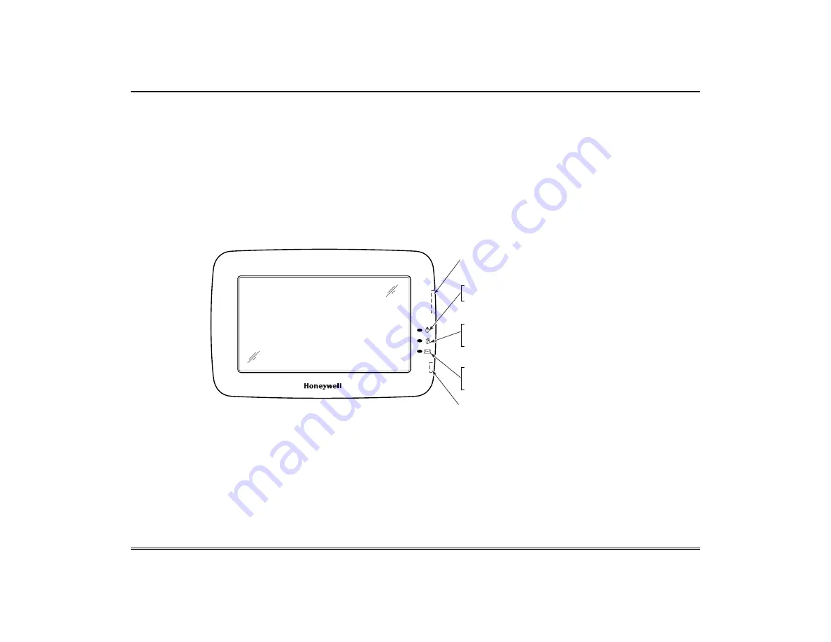
LED Operation 

The Tuxedo Touch Keypad has three LEDs as follows: 

6280-001-V0

FLASHING – The system contains new
message(s) for the User.
OFF – No new messages.

RESET BUTTON
Press to reset keypad

ON – System is armed.
OFF – System is not armed.

ARMED (RED) LED

READY (GREEN) LED

ON – System is disarmed and ready to arm.
OFF – System is armed or disarmed but not
ready. If disarmed, faults or troubles are present.

MESSAGE (YELLOW) LED

SD/SDHC CARD Slot


NOTE:

 If the Screen Blackout (*EN50131 Display) feature is enabled (see below) the keypad returns to the “Home” screen and 

the  “Armed” and “Ready” status LEDs turn OFF after 30 seconds. The keypad will remain in this state until a valid user code is 

entered. 

*The EN50131 Display compliance feature is a European Standard designed to prevent unauthorized users from viewing the 

status of the Security System. 


Safe Mode 

The Keypad contains a Safe Mode of operation. In the rare event that the keypad cannot successfully communicate in its graphic 
mode with the control panel, the Safe Mode is a backup mode that ensures that you can communicate with your system. Refer to 

the 

Safe Mode

 section for further information. 

Summary of Contents for Tuxedo

Page 1: ...T Tu ux xe ed do o T To ou uc ch h W WI IF FI I H Ho om me e A Au ut to om ma at ti io on n S Sy ys st te em m User Guide 800 10301V3 4 13 Rev A ...

Page 2: ......

Page 3: ...fe Mode 10 SECURITY 11 Introduction to Security System Operation 11 How to Arm the System 12 How to Arm Multiple Partitions 12 How to Display Faults 13 How to Bypass Zones 13 How to Clear Bypassed Zones 14 How to Disarm the System 14 To disarm Multi Partitions do the following 15 How to Check the Status of Other Partitions 15 Fire and Carbon Monoxide Alarm Operation 16 In Case of Fire Alarm 16 Sil...

Page 4: ...isplay Audio Setup 19 Operation Modes 19 Language Selection if applicable 20 Adjust the Screen Timeouts 20 Clean Screen 20 Routine Care 20 System Information 21 IP Setup and Network Connections 21 Multi Media 24 Voice Messages 24 Video Audio Setup 25 Picture Setup 25 Camera Setup 26 User Setup 28 Authority Levels 28 How to Add a User 28 How to Add an Existing User to a Second Keypad 29 How to Dele...

Page 5: ...te a Honeywell Thermostat 36 Exclude All Z Wave Devices 37 Abort a Z Wave Action 37 Create a Scene 37 Scene Setup Options 38 Create a Group 39 Setting a Secondary Keypad Controller 40 Updating Keypads Controllers with New or Removed devices 40 Removing a Secondary Keypad Controller 41 Output List 41 Z Wave Troubleshooting 41 Remote Services 42 Compatible Devices 44 NOTES 45 GLOSSARY 46 NOTE This d...

Page 6: ...nd cameras Thermostats temperature control for energy conservation when away from home Lights Appliances turn lights and appliances on when the security system is disarmed Door locks door unlocks when the security system is disarmed Cameras control and view up to four cameras in quad view at the same time from any web enabled device In addition this system offers you burglary protection and may pr...

Page 7: ...you to display personal photos in a slide show format and view video files via the external SD SDHC card It is recommended that you use the SD SDHC card supplied with the keypad In everyday handling memory cards can become susceptible to malfunction and or failure due to electrostatic discharges and the information on the card may be lost In some extreme cases the keypad may need to be reset NOTE ...

Page 8: ...een Picture Allows user to display personal photos in a slide show format Panic Displays Emergency functions as programmed by the installer Note This icon is displayed and active on all screens except while in the Clean Screen mode during an LCD Display test in Diagnostics and from the Video and Camera screens Message Record and retrieve Voice Messages Voice Status Allows user to hear system statu...

Page 9: ... Expander Failure The system has a failure in an expansion module Low Battery The system battery that powers the system during an AC power loss is low LRR Supervision Failure The Communication Device used to communicate with the central station has a supervision failure Max Attempts Exceeded The system has exceeded the maximum attempts to communicate with the Central Station Pager Failure The syst...

Page 10: ...tem contains new message s for the User OFF No new messages RESET BUTTON Press to reset keypad ON System is armed OFF System is not armed ARMED RED LED READY GREEN LED ON System is disarmed and ready to arm OFF System is armed or disarmed but not ready If disarmed faults or troubles are present MESSAGE YELLOW LED SD SDHC CARD Slot NOTE If the Screen Blackout EN50131 Display feature is enabled see ...

Page 11: ...tly have the installer describe the actual settings of this mode Yes Yes set for Away or Stay Mode No set for Instant or Maximum Mode Yes Yes set for Away or Maximum Mode No set for Stay or Instant Mode Important On Commercial systems Away Auto Stay mode is shown as Away mode with all zones monitored However some interior zones may not be armed Note The Voice Status Icon indicates the Voice featur...

Page 12: ... the last 10 seconds of Exit Delay When exit delay time expires the screen automatically changes to indicate the system is Armed Note For CP 01 installations Maximum Mode cannot be used How to Arm Multiple Partitions Note Some systems may not have multiple partitions and the Arm Multi Partitions icon may not be displayed To arm multiple partitions ICON ACTION NOTES 1 From the Home screen press the...

Page 13: ... SELECTED icon Show Zones Icons Distressed Zones Icons Clear Bypasses Refresh Data Bypass Selected Bypass All Distressed Zones Alarm Troubles Faults Bypass Zones Low Battery All How to Bypass Zones The Bypass function is used when you want to arm your system with one or more zones left open Bypassed zones are unprotected and do not cause an alarm when violated while your system is armed Residentia...

Page 14: ...llows ICON ACTION NOTES 1 Press the SHOW ZONES icon While the keypad is requesting and receiving the zone data from the control panel the screen displays Please Wait Then the zones along with their current status are displayed 2 Press the CLEAR BYPASSES icon 3 Enter your 4 digit user code The More Choices screen is displayed showing the system as Ready to Arm Note If the system is armed and you un...

Page 15: ...Check the Status of Other Partitions This system supports between one and eight Partitions depending on the system Partitioning enables a single physical alarm system to control up to eight areas of protection partitions depending on the system you have purchased Each Touch Screen keypad is assigned a default partition for display purposes and shows only that partition s information Note A letter ...

Page 16: ...rupted sound is also produced by optional exterior sounders EVACUATE ALL OCCUPANTS FROM THE PREMISES IMMEDIATELY Notify your Central Station Security Company immediately and wait for further instructions UL CO annunciation has not been investigated by UL and may not be used for UL installations In Case of Fire Alarm 1 A FIRE message appears at your keypad and remains on until you silence the alarm...

Page 17: ... do the following ICON ACTION NOTES 1 To clear press CLEAR 2 Enter your Authorized Code or 3 To hide press HIDE to clear the Control Panel Message later Once your Authorized Code is accepted the Control Panel Message is cleared If the alarm is still present press CLEAR again and then enter your Authorized Code again Press the HIDE icon to address the condition later Advanced System Features While ...

Page 18: ...s 3 Press the SHOW MORE button to view all items and press the up down arrows to scroll through the event log When All Partitions or All Events icon is pressed and more than 100 events exist the Next and Previous icons are displayed showing the next 100 or previous 100 events How to Send Emergency Messages An emergency message for fire panic or medical can be sent to the central monitoring station...

Page 19: ...y Audio Setup Operation Modes Operation modes provides access to Chime Mode Voice Mode and Voice Chime which allows you to turn the keypad chime mode and voice mode on or off Chime Mode Keypad chimes whenever a door or window is open Voice Mode Keypad voice annunciates whenever a change in system status occurs Voice Chime The chime mode and voice mode are in effect with the chime beeps followed by...

Page 20: ...de Auto Slideshow After is preset to 1 minute and can not be changed Clean Screen With the exception of normal cleaning the keypad is maintenance free Clean the touch screen as follows ICON ACTION NOTES 1 From the Home screen press the Setup icon 2 Press the Disp Audio Setup icon 3 Enter your Authorized Code if required 4 Press the CLEAN SCREEN icon to disable the keypad for 30 seconds so you can ...

Page 21: ...l UL Note Web Server Hosting is not Listed for use in UL installations Remote Arming Disarming Programming is not to be used in UL Listed installations IP Address Setup In most cases IP addresses are assigned automatically Automatic IP Address Or you may require a Static Fixed IP Address that can be found by accessing your router Refer to your router instructions To connect a mobile device to the ...

Page 22: ...ubnet Mask Default Gateway DNS Server and Port press GO 2 Press the Save icon the IP information will automatically update 3 At your PC Smart Phone or Tablet browser start your browser and enter your IP Address A pop up window displays This will switch off WLAN Network do you want to continue Yes or No Use the Data Entry Keyboard to enter the required information Press the up arrow to switch to ca...

Page 23: ...ete backspace Press the ABC 123 key to switch between numerals and symbols characters Press GO to return to the IP Setup screen A pop up window displays Network Details Saved A pop up window displays the message Settings saved Select OK to save Note To change the default port number 6280 press the field next to port number and on the data entry keyboard enter a secondary port number between 5000 6...

Page 24: ...layed above the message list window To record additional messages repeat steps 3 and 4 The message indicator flashes and the message is listed in the message list window Use the slide bar to raise and lower the message volume As the message is being played a Play Voice Memo message is displayed above the message list window When the end of the message is reached the playback stops Note The Message...

Page 25: ... resolution should not exceed 400 x 240 Videos can not be played when the EN50131 Display is turned ON Video Icons Play Pause Full View Repeat Stop Use the slide bar to scroll through the video list Press the appropriate icon to Play Pause view a Full View Stop or Repeat the video To exit Full View mode at any time while a video is playing press anywhere on the screen Picture Setup This feature al...

Page 26: ... is a first time setup you will need to Discover Configure the cameras prior to mounting and then follow the steps below ICON ACTION NOTES 1 Connect a Cat5 6 cable to the back of your camera LAN and connect the opposite end to the Ethernet on your router 2 Apply power to the Camera It may take a few seconds for initial power up of camera 3 Press the Multimedia and Camera icons or press the Camera ...

Page 27: ...ON FRAME RATE HTTP Port if known A pop up window displays For remote camera viewing service please contact your alarm company and ask for Total ConnectTM service and provide this camera s MAC ID 00c0027fcd15 Press Continue to prepare the camera for Total Connect service Press CONTINUE or CANCEL Security System information for WEP enter Disabled WPA personal WPA2 personal and WEP Key For WPA PSK TK...

Page 28: ...ent authority level name found in your alarm system manuals The authority levels that can be assigned are as follows Authority Level Functions Equivalent System Name Residential Systems Commercial Systems Master Can perform all security functions add delete users in assigned partition program scheduled events and change partition master code Partition Master Level 1 Master Normal Perform security ...

Page 29: ...r Setup and enter the same user name and same user code refer to How to Add a User above The second keypad will automatically update the user information Press Save How to Delete a User ICON ACTION NOTES 1 Select the User you want to delete 2 Press the DELETE USER icon 3 Enter your Authorized code 4 Press the appropriate icon The Confirm Delete screen is displayed Three selections are available ad...

Page 30: ...with Yes the keypad enters into the Safe Mode If you answer with No the keypad tries to communicate with the panel again After 3 consecutive times of receiving no response the keypad enters the Safe Mode automatically Note Use care when providing the Yes or No response Pressing the screen outside the prescribed area may cause the background to come to the front If this occurs the Yes No message th...

Page 31: ...t the Start DST time and then the End DST time by pressing the Month Weekend and Hour that you want DST to start 5 APPLY saves the settings Make sure DST On is checked to enable this feature Setting Current Time and Date To set the current time do the following ICON ACTION NOTES 1 Press the Time Date Setup icon enter your Authorized Code 2 Press the Month arrow and select the current month 3 Press...

Page 32: ...tem and wants to disable the same output for all each keypad needs to be set individually A confirmation window is displayed stating Information Settings saved Press OK to save the setting Output Setup Icons Apply OK Back Home If the Back icon is pressed a confirmation window appears stating Output Settings changed Do you want to save new settings Select Yes or No Power Mode Setup Power Setup Mode...

Page 33: ...ude a Light Switch or Outlet Module Install a Z Wave Lamp module Switch or Outlet module as described below ICON ACTION NOTES 1 At the Tuxedo Touch Keypad a Press the Automation icon from the Home screen and then press the Z Wave Setup icon to display Z Wave Device Management screen b Press the Z Wave Include Add icon 2 At the device Module a Press the Function Key on the device Note Z Wave light ...

Page 34: ...unction key on device Adding to Security Network Device added successfully Enrollment procedure may vary depending on the door lock device Refer to the door lock instructions for enrollment procedure Note If software is upgraded on the Tuxedo Touch keypad re include the door lock and re set the user code in the door lock Include a Honeywell Thermostat Install Honeywell Thermostat according to the ...

Page 35: ... Device added successfully UL Access control functionality has not been evaluated by UL and may not be used in UL Listed applications Editing Z Wave Device Names Edit a Device Module Name To edit a device name do the following ICON ACTION NOTES 1 At the Tuxedo Touch Keypad a Press the Automation icon from the Home screen and press the Z Wave Setup icon to display the Z Wave Device Management scree...

Page 36: ...he default setting Notes If the device is not excluded refer to Z Wave Troubleshooting When excluding the door lock the user code associated with the door lock will remain in the system If needed refer to the panel Installation Instructions on how to remove this user code To remove a defective device refer to the section on Troubleshooting 2 Highlight the device to exclude and press the Z Wave Exc...

Page 37: ...iggers and Actions When the trigger condition occurs the action is executed To define a Scene do the following Scene Icons Condition Trigger Action Icons ADD DELETE EDIT LOG Add Edit Delete Save ICON ACTION NOTES 1 At the Tuxedo Touch Keypad a Press the Automation icon and then press the Scene Setup icon to display the Scene Setup screen b Press the Add icon to set up a Scene c Press the Name box ...

Page 38: ...as selected Enter Date The Time can be set to edeute automatically at Sunrise or Sunset by pressing the Sunrise Sunset option Note The Sunrise Sunset feature is dependent on the Region selected in the Weather Forecast section and requires internet access for accuracy Press the BY CLOCK button to limit the scene to execute only from within a specified time window and press on the hour minutes displ...

Page 39: ...fter each selection press SAVE In the Action box press the Add icon To set the security mode press the SECURITY button and select DISARM AWAY STAY NIGHT Enter User Code if required To set the light on off press the LIGHT button and select a Light Device from the drop down menu set the action to ON OFF To set the thermostat settings press the THERMOSTAT button and select a Thermostat from the drop ...

Page 40: ...e Remote Services section Note Up to 232 Secondary Controllers can be added The message is displayed Please remove all Z wave devices from network first 2 At Controller 2 a Remove any Z Wave devices that have been added b Press the Z Wave Primary icon located in the lower right side of the screen c Select Yes to change this keypad to a Secondary Controller The message is displayed Scanning for Dev...

Page 41: ...new device Make sure the Z Wave device is within range of the Tuxedo Touch keypad You may need to move the device closer to the keypad Refer to the Z Wave device Instruction Guide for proper range Device is within proper range but still is not included 1 At the Tuxedo Touch Keypad a Press the Automation icon from the Home screen and then press the Z Wave Setup icon to display the Z Wave Device Man...

Page 42: ...in Total Connect Scenes created in Tuxedo View Edit Scenes View Edit Scenes Total Connect yes yes no no Tuxedo yes no yes yes Note For troubleshooting purposes Total Connect server information including IP addresses can be viewed on the Total Connect Server Setup screen by pressing the TC Server Info button see next page Remote Services Setup NOTE If used for Remote Services Tuxedo Touch WiFi shou...

Page 43: ...been created in Total Connect 1 From the Home screen press the Automation and Scene Setup icons then press the Remote button The screen displays a list of scenes created in Total Connect NOTE The Local button allows you to view a list of scenes created in Tuxedo 2 To control a Remote scene select the desired scene then click the appropriate action ex Run Enabling Devices for Total Connect 1 From t...

Page 44: ...ck Yale Real Living Touchscreen Lever Lock Yale Real Living Push Button Deadbolt Lock Yale Real Living Touchscreen Deadbolt Lock Schalge Link Deadbolt Lock Schlage Link Lever Lock Kwikset Smartcode Lever lock Kwikset Smartcode Deadbolt Lock Thermostats Honeywell ECC Wayne Dalton Zwave thermostat Trane Zwave Thermostat Appliance HomeManageable Appliance Module Wayne Dalton Small Appliance Module GE...

Page 45: ...etween the remote and the destination device will reduce the maximum range of 100 feet by approximately 25 30 Brick tile or concrete walls block more of the RF signal than walls made of wooden studs and drywall Wall mounted Z Wave devices installed in metal junction boxes will suffer a significant loss of range approximately 20 since the metal box blocks a large part of the RF signal WARNING NOT F...

Page 46: ...en The screen that is normally displayed on the keypad when entries are not being made The keypad returns to this screen when the Home icon is pressed or when an entry is not received for a pre set period of time Gateway Address Sometimes called a router a gateway is a computer and or software used to connect two or more networks which translates information from one network to the other A Gateway...

Page 47: ...installed Reorient the receiving antenna until interference is reduced or eliminated Move the radio or television receiver away from the receiver control Move the antenna leads away from any wire runs to the receiver control Plug the receiver control into a different outlet so that it and the radio or television receiver are on different branch circuits Consult the dealer or an experienced radio T...

Page 48: ...OF OR RELATING IN ANY WAY TO THE PRODUCT AND OR FOR BREACH OF THIS OR ANY OTHER WARRANTY OR CONDITION EXPRESS OR IMPLIED OR UPON ANY OTHER BASIS OF LIABILITY WHATSOEVER EVEN IF THE LOSS OR DAMAGE IS CAUSED BY SELLER S OWN NEGLIGENCE OR FAULT AND EVEN IF SELLER HAS BEEN ADVISED OF THE POSSIBILITY OF SUCH LOSSES OR DAMAGES Any product description whether in writing or made orally by Seller or Seller...

Reviews: