background image

Honeywell


Industrial Measurement and Control 


MU1I-6214 

Honeywell-1100 Virginia Drive-Fort Washington, PA 19034 


02/03 


¾

 3 - PID CONTROL TUNING 

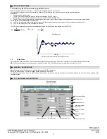
3.1 Determining the PID parameters using ON/OFF control 

Ensure that the setpoint is at a safe level, to avoid any possible damage due to overshoot. 
This method of tuning can be used to calculate the optimum PID parameters only if the process can tolerate large disturbances. 

Procedure:


1.  Enter a required setpoint value. 
2.  The UDC100 tuning parameters must be configured to achieve ON/OFF control. 
 

Set the PB = 0.0% via the UDCs MMI or by means of the UDC100 CONFIGURATOR. 

3.  The UDC100 will cause the process to oscillate around the setpoint, the oscillation obtained will be dependent on the process characteristics. 

Formula used to calculate optimum PID values:


a)  Let "P" be the difference between the highest value of the first overshoot and the lowest value of the first undershoot expressed in °C. 
b)  Let "T" be the time period of the oscillations in seconds. 
 
The PID control parameters should be then calculated using the table below and then entered into the UDC100. 

Pb

P

Intervalo

100 %

=


rSt

T s

  =    


 rtE 

T

6

s

=


On/off control

Time (s)

P

ro

c

es

s va

ri

a

b

le

 (

%

)

T

P


Determining PID parameters with ON/OFF control 


3.2 Output 

bias 

The output bias parameter can be used to eliminate the offset between the PV and SP when the controller is in proportional and derivative mode. 

NB:

 The output bias (manual res et) parameter is accessible via the UDC100 MMI only when the integral time constant is set to 0. 


¾

 4 - MANUAL CONTROL MODE 

Note:

 Switching from PID to Man control and from Man control to PID is bumpless. 

During the manual mode, the "Man" message flashes alternatively with the PV. 
To adjust the output power, press the push button corresponding to the required loop, the last output value will be displayed, the value can then be adjusted using 
the setpoint knob. 


¾

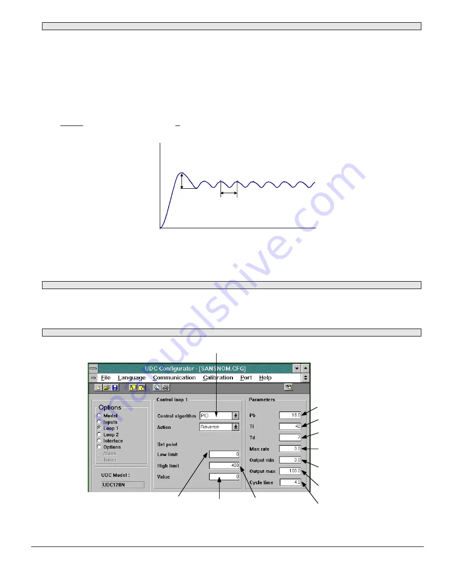
 5 - PC CONFIGURATOR DESCRIPTION 

Choice of control

(default: ON/OFF)

Proportional Band

Integral time

Derivative time

Maximum output
increment

Minimum output
power

Maximum output
power

Output cycle time

Setpoint value

Setpoint low limit

Setpoint high limit


Summary of Contents for UDC100

Page 1: ...secutive input output updates configured from 0 to 100 in 0 1 increment Setpoint low limit Configurable minimum setpoint value in 1 C increment Setpoint high limit Configurable maximum setpoint value In 1 C increment Setpoint Setpoint value used for control in 1 C increment Output power high limit Power output high limit configurable from 0 to 100 output in 0 1 increment Output power low limit Pow...

Page 2: ... of the oscillations in seconds The PID control parameters should be then calculated using the table below and then entered into the UDC100 Pb P Intervalo 100 rSt T s rtE T 6 s On off control Time s Process variable T P Determining PID parameters with ON OFF control 3 2 Output bias The output bias parameter can be used to eliminate the offset between the PV and SP when the controller is in proport...

Page 3: ... est utilisée pour réajuster la valeur de procédé à la valeur du point de consigne dans un laps de temps plus court après une perturbation dans le procédé La fonction est aussi utilisée pour limiter le dépassement de la valeur de procédé pendant le démarrage initial de ce procédé Le fonctionnement de l action dérivée est basé sur la vitesse de changement de la valeur de procédé par rapport au poin...

Page 4: ... pour régler la sortie de temps proportionnel afin d optimiser la régulation Appuyez sur le bouton 1 pour retourner en mode de fonctionnnement normal ou attendez que le message no apparaisse Après quelques instants l UDC100 retourne en mode normal PID Il est possible de passer de yes à no en appuyant sur le bouton 1 Remarque Si yes est sélectionné l UDC100 entre en mode manuel dès que l on sort du...

Page 5: ...NUELLE Remarque Le passage du mode de régulation PID au mode Station manuelle et vice versa se fait sans à coups En mode manuel le message Man clignote en alternance avec la valeur de procédé Pour régler la puissance de sortie appuyez sur le bouton correspondant à la boucle utilisée La dernière valeur de sortie est affichée cette valeur peut ensuite être réglée avec le bouton central 5 DESCRIPTION...

Page 6: ...en Sollwert einzuregeln oder bei Anfahrprozessen ein Überschwingen zu vermeiden Die Vorhaltwirkung beruht auf der Änderungsgeschwindigkeit der Abweichung zwischen Ist und Sollwert Die Vorhaltzeit ist von 0 Sekunden bis 5999 Sekunden einstellbar Ist die Vorhaltzeit auf 0 Sekunden eingestellt ist die Vorhaltwirkung ausgeschaltet Dieser Parameter ist nicht verfügbar wenn das Proportionalband auf 0 0 ...

Page 7: ...ste 1 auf yes und wieder zurück geschaltet werden Hinweis Wird yes gewählt geht der UDC100 nach dem Verlassen des Konfigurations Modus in die manuelle Betriebsart Er bleibt in der manuellen Betriebsart bis im Konfigurationsmodus no gewählt wird 3 EINSTELLUNG DER PID REGELUNG 3 1 Ermittlung der PID Parameter über die EIN AUS Regelung Stellen Sie sicher daß der Sollwert in einem Bereich liegt der mö...

Page 8: ...n und den Istwert an Zur Veränderung des Ausgangssignals drücken Sie die dem Regelkreis zugeordnete Taste Der letzte Wert des Ausgangs wird in angezeigt und kann über den Sollwert Einstellknopf verändert werden 5 BESCHREIBUNG DER PC KONFIGURATION Wahl des Regel Algorithmus Standard EIN AUS Proportionalband Nachstellzeit Vorhaltzeit Maximaler Ausgangssprung Untere Ausgangs begrenzung Obere Ausgangs...

Page 9: ...cción derivativa se utiliza para que la VP vuelva a SP más rápidamente tras una alteración del proceso Esta función también se utiliza para limitar la cantidad de sobredesviación de la VP durante la puesta en marcha inicial de un proceso El funcionamiento de la acción derivativa se basa en la velocidad de cambio de la VP con relación al SP La constante de tiempo derivativo puede configurarse de 0 ...

Page 10: ...aparece el menú de banda proporcional se puede modificar este parámetro para ello hay que esperar hasta que el valor se ponga intermitente entonces se puede modificar por medio del mando del punto de consigna Al pulsar el botón 1 mientras se visualiza el mensaje Pb se accede al siguiente parámetro la constante de tiempo integral Para su modificación se puede seguir el mismo procedimiento indicado ...

Page 11: ...superior de la primera sobredesviación y el valor inferior de la primera sobredesviación expresada en C b Sea T el tiempo de duración de las oscilaciones en segundos Los parámetros de control PID se calculan aplicando la siguiente tabla y a continuación se introducen en el UDC100 Pb P Intervalo 100 rSt T s rtE T 6 s Control on off Tiempo s T P Variable para procesar Establecimiento de los parámetr...

Page 12: ...CRIPCIÓN DEL CONFIGURADOR PC Elección del control por defecto ON OFF Banda proporcional Tiempo integral Tiempo derivativo Incremento de salida máximo Corriente de salida mínima Corriente de salida máxima Duración de salida Valor del punto de consigna Límite inferior del punto de consigna Límite superior del punto de consigna ...

Reviews: