xi
UDC3500 Universal Digital Controller Product Manual
3/07
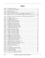
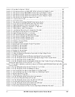
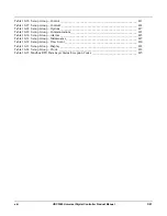
Table 4-9 Procedure for Starting “TUNE” _______________________________________________ 207
Table 4-10 Procedure for Using AUTOMATIC TUNE at Start-up for Duplex Control ____________ 209
Table 4-11 Procedure for Using BLENDED TUNE at Start-up for Duplex Control_______________ 210
Table 4-12 Procedure for Using MANUAL TUNE for Heat side of Duplex Control ______________ 211
Table 4-13 Procedure for Using MANUAL TUNE for Cool side of Duplex Control ______________ 211
Table 4-14 Procedure for Accessing Accutune Error Codes _________________________________ 212
Table 4-15 Accutune Error Codes _____________________________________________________ 212
Table 4-16 Set Up Procedure _________________________________________________________ 214
Table 4-17 Procedure for Switching PID SETS from the Keyboard ___________________________ 215
Table 4-18 Logic Gates Constraints and Dynamic Operation Status ___________________________ 219
Table 4-19 Digital Input Option Action on Contact Closure _________________________________ 221
Table 4-20 Digital Input Combinations “DIG IN1” or “DIG IN2” ____________________________ 224
Table 4-21 Digital Inputs 1 and 2 Combination ___________________________________________ 225
Table 4-22 Auto/Manual Station Mode Configuration Procedure _____________________________ 227
Table 4-23 Procedure for selecting Two Loop Algorithm ___________________________________ 233
Table 4-24 Digital Display Indication—Two Loops _______________________________________ 234
Table 4-25 Procedure for Displaying Alarm Setpoints _____________________________________ 236
Table 4-26 Procedure for Displaying TPSC Motor Position _________________________________ 238
Table 4-27 Procedure for Setting a Failsafe Value_________________________________________ 239
Table 4-28 Procedure for Setting a Failsafe Mode_________________________________________ 240
Table 4-29 Running A Setpoint Ramp __________________________________________________ 245
Table 4-30 Program Contents_________________________________________________________ 247
Table 4-31 Ramp/Soak Profile Example (Using 12 Segments) _______________________________ 250
Table 4-32 Program #1 Record Sheets __________________________________________________ 251
Table 4-33 Program #2 Record Sheets __________________________________________________ 253
Table 4-34 Program #3 Record Sheets __________________________________________________ 255
Table 4-35 Program #4 Record Sheets __________________________________________________ 257
Table 4-36 Run/Monitor Functions ____________________________________________________ 259
Table 5-1 Voltage, Milliamp and Resistance Equivalents for Input Range Values _______________ 278
Table 5-2 Equipment Needed _________________________________________________________ 280
Table 5-3 Set Up Wiring Procedure for Thermocouple Inputs Using an Ice Bath ________________ 282
Table 5-4 Set Up Wiring Procedure for Thermocouple Inputs using a Thermocouple Source _______ 283
Table 5-5 Set Up Wiring Procedure for RTD Inputs _______________________________________ 284
Table 5-6 Set Up Wiring Procedure for Radiamatic, Millivolts, Volts, Carbon, Oxygen or Thermocouple
Differential Inputs (Except 0-10 Volts and –1 to 1 Volts) ________________________________ 285
Table 5-7 Procedure to determine calibration voltages for Thermocouple Differential input types other than the
Factory Setting _________________________________________________________________ 286
Table 5-8 Set Up Wiring Procedure for 0 to 10 Volts or –1 to 1 Volts _________________________ 287
Table 5-9 Set Up Wiring Procedure for Milliampere Inputs _________________________________ 288
Table 5-10 Set Up Wiring Procedure for Dual High Level Voltage Inputs ______________________ 289
Table 5-11 Set Up Wiring Procedure for Dual High Level Milliampere Inputs __________________ 290
Table 5-12 Input Calibration Procedure _________________________________________________ 291
Table 5-13 Restore Factory Calibration _________________________________________________ 293
Table 6-1 Set Up Wiring Procedure for the First Current Output _____________________________ 296
Table 6-2 First Current Output Calibration Procedure ______________________________________ 297
Table 6-3 Set Up Wiring Procedure for the Second Current Output ___________________________ 298
Table 6-4 Second Current Output Calibration Procedure ___________________________________ 299
Table 6-5 Set Up Wiring Procedure for the Third Current Output ____________________________ 300
Table 6-6 Third Current Output Calibration Procedure _____________________________________ 301
Table 6-7 Position Proportional and Three Position Step Output Calibration Procedure ___________ 303
Summary of Contents for UDC3500
Page 16: ......
Page 459: ...3 07 UDC3500 Universal Digital Controller Product Manual 443 ...

