Configuration
3/07
UDC3500 Universal Digital Controller Product Manual
109
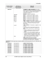
Function Prompt
Lower Display
Selections or
Range of Setting
Upper Display
Parameter
Definition
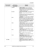
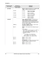
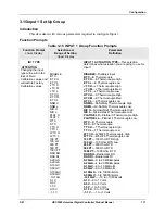
RLYSTATE
1OF 2OF
1ON 2OF
1OF 2ON
1ON 2ON
DIGITAL OUTPUT STATUS AT 0 % OUTPUT
—
Allows the following selections:
1OF 2OF
Output 1 de-energized
Output
2
de-energized
1ON 2OF
Output 1 energized
Output
2
de-energized
1OF 2ON
Output 1 de-energized
Output
2
energized
1ON 2ON
Output 1 energized
Output
2
energized
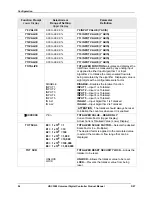
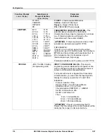
RLY TYPE
RELAY CYCLE TIME INCREMENT
—Used only for
Time Simplex and Duplex output configurations. This
configuration sets the increment size of the relay
cycle times in the Tuning and Tuning 2
Set Up
groups.
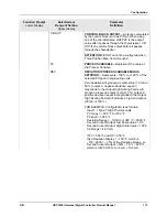
MECHAN
ELECTROMECHANICAL RELAY
—Cycle time in
one-second increments.
SOL ST
SOLID STATE RELAY
—Cycle time in 1/3-second
increments. This is useful for solid-state relay
applications that require shorter cycle times. DO
NOT use this setting unless cycle times of less than
1 second are required.
ATTENTION
The Lockout selection must be set to
NONE in order to view this selection.
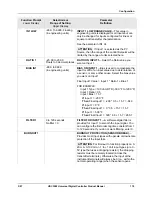
MOTOR TI
5 to 1800 seconds
MOTOR TIME
—Appears only when “POSPROP” is
selected as the Output algorithm. This is the time it
takes the motor to travel from 0 to 100% (fully closed
to fully open). This time can usually be found on the
nameplate of the motor.
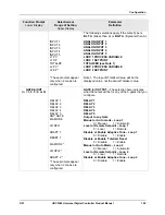
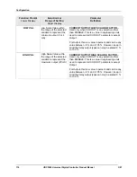
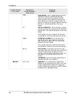
OUT2 ALG
NONE
TIME
CURRENT
TIME D
CUR D
CUR TI
TI CUR
OUTPUT ALGORITHM
—Selects the type of output
desired for the second control loop.
See OUT ALG for definitions.
NONE
TIME SIMPLEX
CURRENT SIMPLEX
TIME DUPLEX
CURRENT DUPLEX
CURRENT/TIME DUPLEX
TIME/CURRENT DUPLEX
ATTENTION
Some of these configurations may not
be available on Loop 2 if Loop 1 uses the available
outputs. See Table 2-6 and Table 2-7 for information
about output types and how they are used for each
Loop.
Summary of Contents for UDC3500
Page 16: ......
Page 459: ...3 07 UDC3500 Universal Digital Controller Product Manual 443 ...

