Configuration
122
UDC3500 Universal Digital Controller Product Manual
3/07
Function Prompt
Lower Display
Selections or
Range of Setting
Upper Display
Parameter
Definition
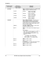
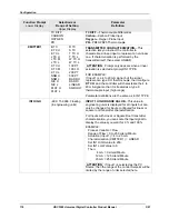
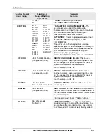
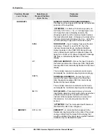
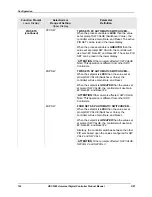
TC DIFF
PR
TC DIFF
—Thermocouple Differential
PR
—PR40-PR20 Thermocouple
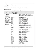
XMITTER2
B TC
E TC H
E TC L
J TC H
J TC M
J TC L
K TC H
K TC M
K TC L
NNM H
NNM L
NIC H
NIC L
PLAT H
PLAT L
R TC
S TC
T TC H
T TC L
W TC H
W TC L
100 PT
100 LO
200 PT
500 PT
RAD RH
RAD RI
LINEAR
SQROOT
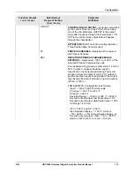
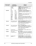
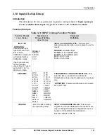
TRANSMITTER CHARACTERIZATION
—This
selection lets you instruct the controller to
characterize a linear input to represent a non-linear
one. If characterization is performed by the
transmitter itself, then select LINEAR.
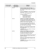
ATTENTION
Prompt only appears when a linear
actuation is selected at prompt IN1 TYPE.
FOR EXAMPLE:
If Input 2 is a 4 to 20 mA signal, but the signal
represents a type K H thermocouple, then configure
K TC H
and the controller will characterize the 4 to
20 mA signal so that it is treated as a type K
thermocouple input (high range).
Parameter definitions are the same as in IN2 TYPE.
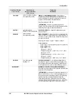
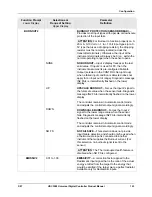
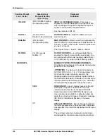
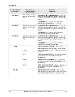
IN2 HIGH
–999. To 9999. Floating
(in engineering units)
INPUT 2 HIGH RANGE VALUE
—This value in
engineering units is displayed for all inputs but can
only be changed for inputs configured for linear or
square root transmitter characterization.
See the example in IN1 HI.
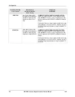
IN2 LOW
–999. To 9999. Floating
(in engineering units)
INPUT 2 LOW RANGE VALUE
—This value in
engineering units is displayed for all inputs but can
only be changed for inputs configured for linear or
square root transmitter characterization.
See the example in IN1 HI.
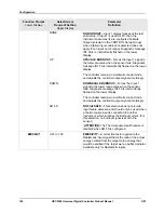
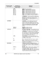
RATIO 2
–20.00 to 20.00
Floats to 3 decimal places
RATIO ON INPUT 2
—Select the Ratio value you
want on Input 2.
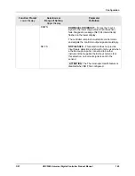
BIAS IN2
–999. to 9999.
(in engineering units)
BIAS ON INPUT 2
—Bias is used to compensate the
input for drift of an input value due to deterioration of
a sensor, or some other cause. Select the bias value
you want on Input 2.
Final Input 2 Value = Input 2 * Ratio 2 + Bias 2
FILTER 2
0 to 120 seconds
No filter = 0
FILTER FOR INPUT 2
—A software digital filter is
provided for Input 2 to smooth the input signal. You
can configure the first order lag time constant from 1
to 120 seconds. If you do not want filtering, enter 0.
Summary of Contents for UDC3500
Page 16: ......
Page 459: ...3 07 UDC3500 Universal Digital Controller Product Manual 443 ...


