Configuration
140
UDC3500 Universal Digital Controller Product Manual
3/07
Function Prompt
Lower Display
Selections or
Range of Setting
Upper Display
Parameter
Definition
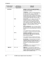
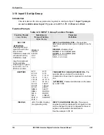
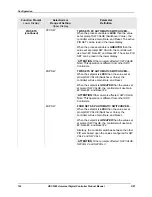
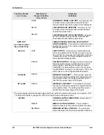
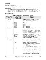
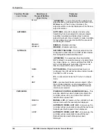
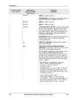
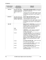
OUT HYST
0.0 to 100.0 % of PV span
HYSTERESIS (OUTPUT RELAY)
is an adjustable
overlap of the ON/OFF states of each control output.
This is the difference between the value of the
process variable at which the control outputs
energize and the value at which they de-energize.
Only applicable for ON/OFF control.
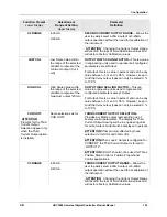
FAILMODE
NoLATCH
FAILSAFE MODE
NON-LATCHING
—Controller stays in last mode that
was being used (automatic or manual); If unit was in
Automatic mode, then the output goes to the failsafe
value. (NOTE 1, NOTE 2)
LATCH
LATCHING
—Controller goes to manual mode; If unit
was in Automatic mode, then the output goes to the
failsafe value. (NOTE 2)
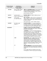
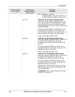
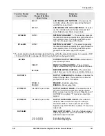
FAILSAFE
0 to 100 %
FAILSAFE OUTPUT VALUE
—The value used here
will also be the output level when you have
Communications SHED set to failsafe or when NO
BURNOUT is configured and the PV Source fails.
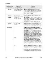
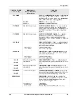
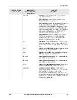
ATTENTION
Applies for all output types
except
Three Position Step Control.
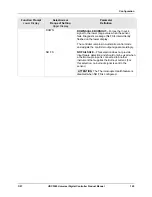
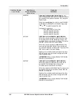
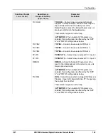
0 PCT
100 PCT
THREE POSITION STEP FAILSAFE OUTPUT
0 PCT
—Motor goes to closed position.
100 PCT
—Motor goes to open position.
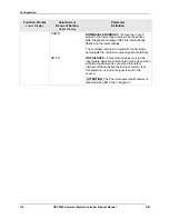
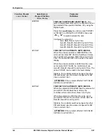
SW FAIL
0 PCT
100 PCT
Position Proportional motor position when slidewire
fails.
0 PCT
—Motor goes to closed position.
100 PCT
—Motor goes to open position.
ATTENTION
PWR OUT must be configured for
FSAFE.
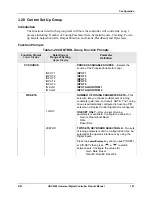
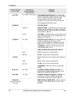
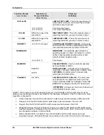
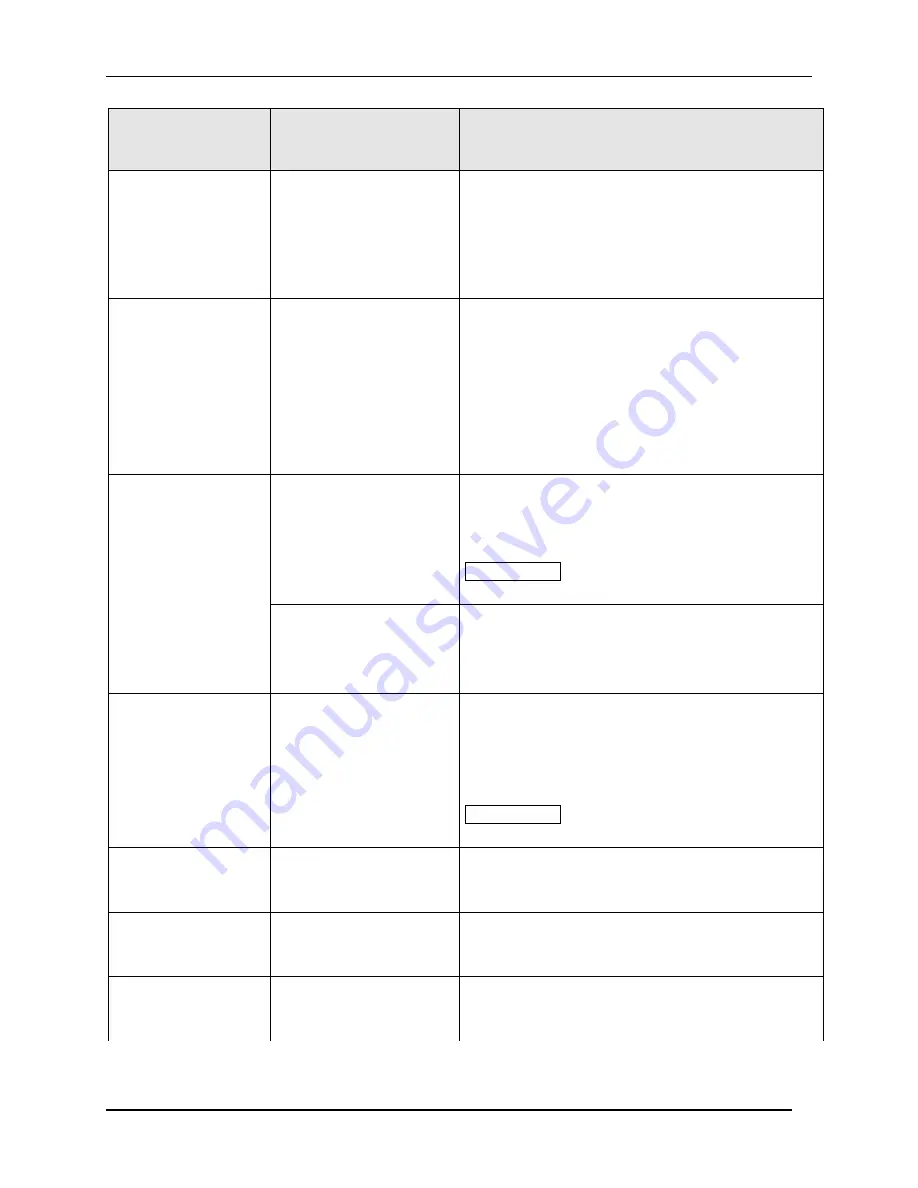
MAN OUT
0 to 100 %
POWER-UP PRESET MANUAL OUTPUT
—At
power-up, the controller will go to manual and the
output to the value set here. (NOTE 1)
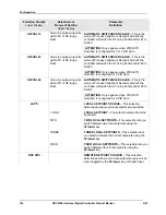
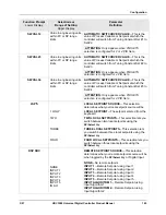
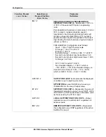
AUTO OUT
0 to 100 %
POWER-UP PRESET AUTOMATIC OUTPUT
—At
power-up, the controller will begin its automatic
control at the output value set here. (NOTE 1)
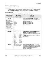
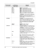
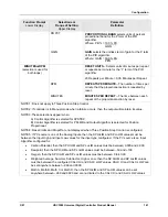
PBorGAIN
(selection is used for
both loops)
PROPORTIONAL BAND UNITS
—Select one of the
following for the Proportional (P) term of the PID
algorithm:
Summary of Contents for UDC3500
Page 16: ......
Page 459: ...3 07 UDC3500 Universal Digital Controller Product Manual 443 ...

