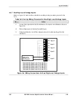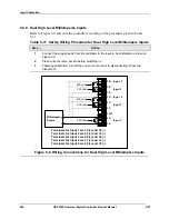
Input Calibration
3/07
UDC3500 Universal Digital Controller Product Manual
291
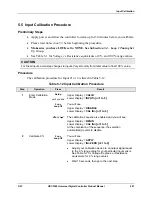
5.5 Input Calibration Procedure
Preliminary Steps
•
Apply power and allow the controller to warm up for 30 minutes before you calibrate.
•
Please read
Subsection 5.3
before beginning the procedure.
•
Make sure you have LOCK set to NONE. See Subsection 3.4 – Loop 1 Tuning Set
Up Group
.
•
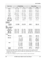
See Table 5-1 for Voltage vs. Resistance equivalents or 0 % and 100 % range values.
CAUTION
For linear inputs, avoid step changes in inputs. Vary smoothly from initial value to final 100 % value.
Procedure
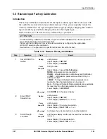
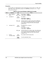
The calibration procedure for Input #1 or 2 is listed in Table 5-12.
Table 5-12 Input Calibration Procedure
Step
Operation
Press
Result
1
Enter Calibration
Mode
Setup
until you see
Upper Display
=
CALIB
Lower Display
=
INPUTn [n=1 to 5]
Func
Loop 1/2
You will see:
Upper Display
=
DISABLE
Lower Display
=
CAL INn [n=1 to 5]
or
The calibration sequence is enabled and you will see:
Upper Display
=
BEGIN
Lower Display
=
CAL INn [n=1 to 5]
At the completion of the sequence, the selection
automatically reverts to disable.
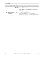
2
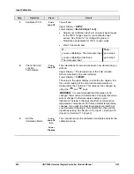
Calibrate 0 %
Func
Loop 1/2
You will see:
Upper Display
=
APPLY
Lower Display
=
INn ZERO [n=1 to 5]
•
Adjust your calibration device to an output signal equal
to the 0 % range value for your particular input sensor.
See Table 5-1 for Voltage, Degrees, or Resistance
equivalents for 0 % range values.
•
Wait 15 seconds, then go to the next step.
Summary of Contents for UDC3500
Page 16: ......
Page 459: ...3 07 UDC3500 Universal Digital Controller Product Manual 443 ...

