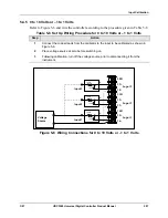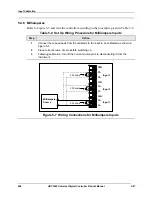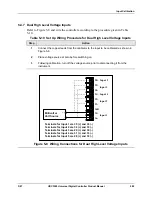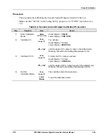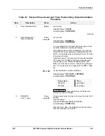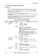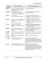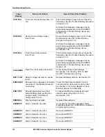
background image

Output Calibration 

300 

UDC3500 Universal Digital Controller Product Manual 

3/07 

6.4  Third Current Output Calibration 

Introduction 

Calibrate the controller so that the output provides the proper amount of current over the 
desired range. The controller can provide a current output range of from 0 mA to 21 mA. 
The controller is usually calibrated at 4 mA for 0 % of output and 20 mA for 100 % of 
output, but it may be calibrated for any other values between 0 mA and 21 mA. It is not 
necessary to re-calibrate the controller in order to change from 4 to 20 mA operation over 
to 0 to 20 mA operation; a simple configuration change is all that is required. See the CO 
RANGE configuration for Third Current Output in 

Sub-section 3.22

 for details. 

Equipment Needed 

You will need a calibrating device with whatever accuracy is required, capable of 
measuring 0 to 20 mA. 

Calibrator Connections 

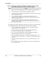
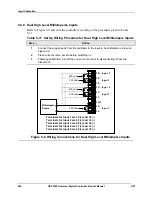
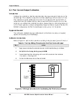
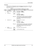
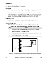
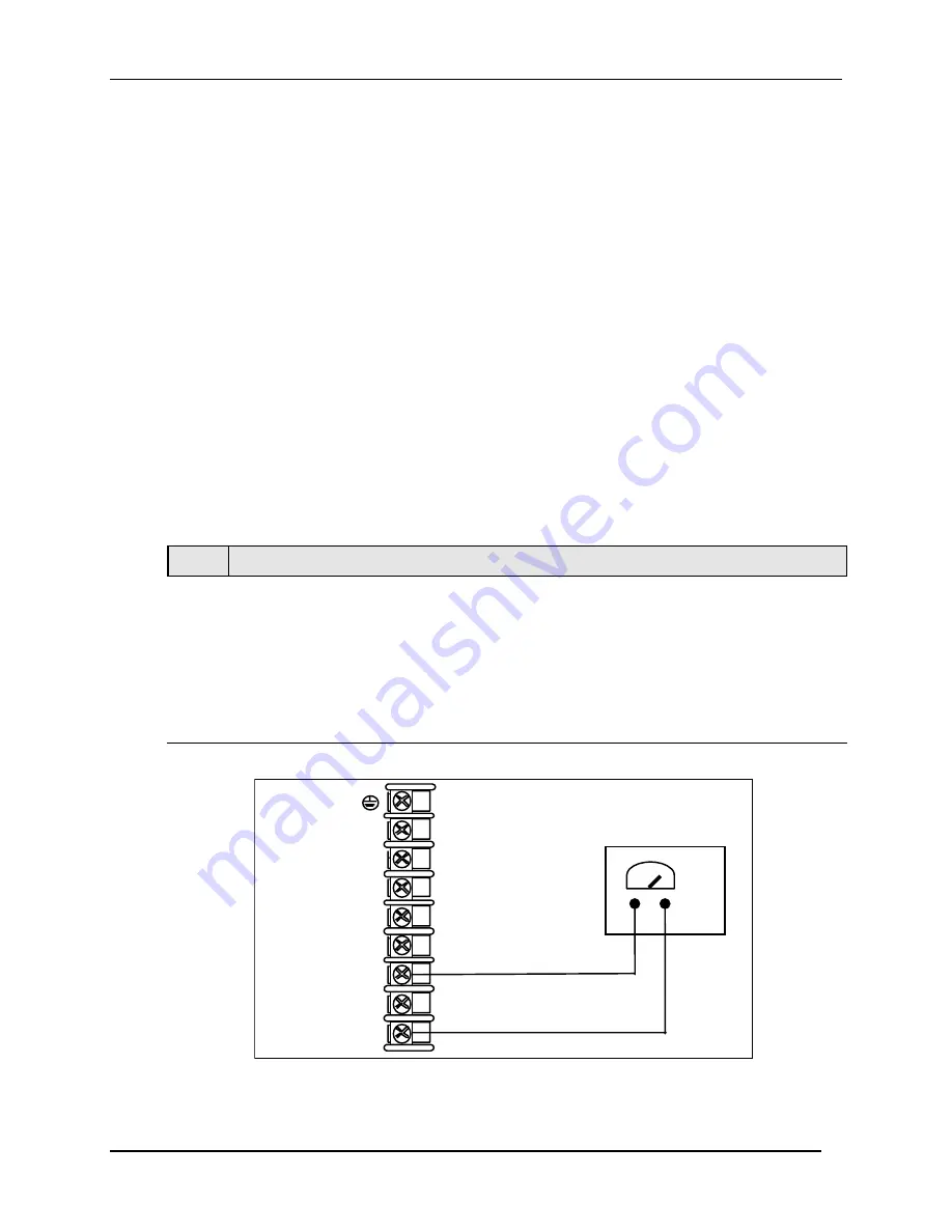
Refer to Figure 6-3 and wire the controller according to the procedure given in Table 6-5. 

Table 6-5  Set Up Wiring Procedure for the Third Current Output 

Step 

Action 

Apply power and allow the controller to warm up 30 minutes before you calibrate. 

Set LOCK in the Tuning Set Up group to NONE. 

Tag and disconnect the field wiring, at the rear of the controller, from terminals 7 (+) 
and 9 (–). See Figure 6-3. 

Connect a milliammeter across these terminals. 


Milliammeter


+

+

_

L2/N


L1

4

5

6

7

8

9

Curre nt 

Output 3 


Figure 6-3  Wiring Connections for Calibrating Third Current Output 

Summary of Contents for UDC3500

Page 1: ...Honeywell Process Solutions Industrial Measurement and Control UDC3500 Universal Digital Controller Product Manual 51 52 25 120 March 2007 ...

Page 2: ...ieu of all other warranties expressed or implied including those of merchantability and fitness for a particular purpose Specifications may change without notice The information we supply is believed to be accurate and reliable as of this printing However we assume no responsibility for its use While we provide application assistance personally through our literature and the Honeywell web site it ...

Page 3: ...Web The following lists Honeywell s World Wide Web sites that will be of interest to our customers Honeywell Organization WWW Address URL Corporate http www honeywell com Industrial Measurement and Control http www honeywell com ps Technical tips http content honeywell com ipc faq Telephone Contact us by telephone at the numbers listed below Organization Phone Number United States and Canada Honey...

Page 4: ...ostatic Discharge ESD hazards Observe precautions for handling electrostatic sensitive devices Protective Earth PE terminal Provided for connection of the protective earth green or green yellow supply system conductor Functional earth terminal Used for non safety purposes such as noise immunity improvement NOTE This connection shall be bonded to protective earth at the source of supply in accordan...

Page 5: ...1 Electrical Considerations 22 2 7 Wiring Diagrams 24 3 CONFIGURATION 44 3 1 Overview 44 3 2 Configuration Prompt Hierarchy 46 3 3 Configuration Procedure 50 3 4 Loop 1 Tuning Set Up Group 51 3 5 Loop 2 Tuning Set Up Group 55 3 6 SP Ramp Set Up Group 58 3 7 SP Program 2 Set Up Group 64 3 8 SP Program 3 Set Up Group 67 3 9 SP Program 4 Set Up Group 70 3 10 Accutune Set Up Group 73 3 11 Algorithm Se...

Page 6: ...Code 194 4 4 Lockout Feature 195 4 5 Monitoring Your Controller 197 4 5 1 Annunciators 197 4 5 2 Viewing the operating parameters 198 4 5 3 Diagnostic Messages 199 4 6 Start Up Procedure for Operation 200 4 7 Control Modes 201 4 7 1 Mode Definitions 201 4 7 2 What happens when you change modes 202 4 8 Setpoints 202 4 9 Timer 204 4 10 Accutune III 205 4 10 1 Tune for Simplex Outputs 207 4 10 2 Tune...

Page 7: ...Ethernet Connection 271 5 INPUT CALIBRATION 277 5 1 Overview 277 5 2 Minimum and Maximum Range Values 278 5 3 Preliminary Information 280 5 4 Input Set Up Wiring 282 5 4 1 Thermocouple Inputs Using an Ice Bath 282 5 4 2 Thermocouple Inputs Using a Thermocouple Source 283 5 4 3 RTD Inputs 284 5 4 4 Radiamatic Millivolts Volts Carbon Oxygen or Thermocouple Differential Inputs 285 5 4 5 0 to 10 Volts...

Page 8: ...log Input 327 7 7 9 Procedure 9 RS 485 328 7 7 10 Procedure 10 Ethernet 330 7 7 11 Procedure 11 Email 331 7 8 Restoring Factory Configuration 332 7 9 Software Upgrades 333 8 PARTS LIST 335 8 1 Exploded View 335 8 2 Removing the chassis 337 9 MODBUS RTU FUNCTION CODES 338 9 1 Overview 338 9 2 General Information 338 9 3 Function Code 20 14h Read Configuration Reference Data 340 9 3 1 Read Configura...

Page 9: ... 10 Logic 395 10 7 11 Output Algorithms 399 10 7 12 Input 1 401 10 7 13 Input 2 403 10 7 14 Input 3 405 10 7 15 Input 4 407 10 7 16 Input 5 409 10 7 17 Control 411 10 7 18 Control Loop 2 414 10 7 19 Options 417 10 7 20 Communications 421 10 7 21 Alarms 423 10 7 22 Maintenance 427 10 7 23 Time Event 430 10 7 24 Display 432 10 7 25 Clock 433 10 8 Modbus RTU Exception Codes 434 11 FURTHER INFORMATION...

Page 10: ...n Prompts ______________________________________________ 99 Table 3 14 OUTPUT Group Function Prompts ___________________________________________ 106 Table 3 15 INPUT 1 Group Function Prompts ___________________________________________ 117 Table 3 16 INPUT 2 Group Function Prompts ___________________________________________ 121 Table 3 17 INPUT 3 Group Function Prompts _____________________________...

Page 11: ...______ 251 Table 4 33 Program 2 Record Sheets __________________________________________________ 253 Table 4 34 Program 3 Record Sheets __________________________________________________ 255 Table 4 35 Program 4 Record Sheets __________________________________________________ 257 Table 4 36 Run Monitor Functions ____________________________________________________ 259 Table 5 1 Voltage Milliamp an...

Page 12: ...arameter ID Address Format for Function Code 20 _______________________ 341 Table 9 4 Register Parameter ID Address Format for Function Code 21 _______________________ 345 Table 10 1 Control Data Parameters ___________________________________________________ 350 Table 10 2 Option Status ____________________________________________________________ 351 Table 10 3 Miscellaneous Read Onlys____________...

Page 13: ..._____________________________________ 421 Table 10 30 Set up Group Alarms ___________________________________________________ 423 Table 10 31 Set up Group Maintenance _______________________________________________ 427 Table 10 32 Set up Group Time Event ________________________________________________ 430 Table 10 33 Set up Group Display ___________________________________________________ 432 Tab...

Page 14: ...tion Connections________________________________ 38 Figure 2 21 Ethernet Communications Option with Adaptor Board_____________________________ 38 Figure 2 22 Ethernet Communications Option without Adaptor Board __________________________ 39 Figure 2 23 Digital Inputs _____________________________________________________________ 41 Figure 2 24 Optional Electromechanical Relay Outputs_______________...

Page 15: ...____________________ 280 Figure 5 2 Wiring Connections for Thermocouple Inputs Using an Ice Bath ____________________ 282 Figure 5 3 Wiring Connections for Thermocouple Inputs Using a Thermocouple Source __________ 283 Figure 5 4 Wiring Connections for RTD Resistance Thermometer Device ____________________ 284 Figure 5 5 Wiring Connections for Radiamatic Millivolts Volts Carbon Oxygen or Thermocou...

Page 16: ......

Page 17: ... can be configured to act as one Universal and four High Level 0 10 Analog Input Accuracy can be Field Calibrated to 0 05 16 bit Analog Input resolution typical Fast scanning rate 166ms Up to 7 Analog and Digital Outputs 4 Digital Inputs Two Math Functions two Characterizers one Polynomial equation and one Totalizer available Two Independent Loops or Cascade Loop Up to four 20 segment Setpoint Pro...

Page 18: ... available as a high level input All actuations and characterizations are keyboard configurable Cold junction compensation is provided for thermocouple type inputs Upscale downscale or failsafe sensor break protection is keyboard configurable A configurable digital filter of 0 to 120 seconds provides input signal damping Thermocouple Health In addition to the standard configurable upscale downscal...

Page 19: ...nctions Characterizers are mutually exclusive with Setpoint Program 4 Digital Inputs Four isolated digital inputs are provided for remote dry contact closure to select one of 25 actions Also two of these digital inputs can allow one of six additional selections to be combined with one of the above selections Outputs Output Types The UDC3500 may have up to seven of the following outputs Current Out...

Page 20: ...niversal Switching Power Operates on any line voltage from 90 to 264 Vac 50 60 Hz without jumpers 24 Vac dc instrument power is available as an option Timer This standard feature provides a configurable time period of 0 to 99 hours 59 minutes or units of minutes and seconds It can be started via the keyboard alarm 2 or by a digital input The timer output is Alarm 1 which energizes at the end of th...

Page 21: ...Body Options CSA certification and UL listing are available as an option Four Sets of Tuning Constants Four sets of PID parameters can be configured for each loop and automatically or keyboard selected Data Security Five levels of keyboard security protect tuning configuration and calibration data accessed by a configurable 4 digit code Nonvolatile EEPROM memory assures data integrity during loss ...

Page 22: ...es independently from Accutune III tuning It does not change the PID constants but temporarily modifies the internal controller response to suppress overshoot This allows more aggressive tuning to co exist with smooth PV response It can be enabled or disabled depending on the application or the control criteria The Second Current Output option is mutually exclusive with the Ethernet Communications...

Page 23: ...exist MAN Or A A Indicates either Manual or Auto mode DI DI Indicates Digital Input 1 and or 2 on SP SP Indicates Local Setpoint 1 Also a bar is lighted when the setpoint being used is shown on the lower display Keys and Functions Func Loop 1 2 Selects functions within each configuration group Switches between Loop Displays for Two Loop and Cascade units Man Auto Man Auto Man Auto Selects Manual o...

Page 24: ...ning on a Pocket PC a Desktop or a laptop computer Create edit configurations live just connect software to the controller via a communications port Create edit configurations offline and download to controller later via a communications port Communication types available on every UDC3500 Infrared standard RS 485 optional Ethernet optional Same port types on UDC2500 and UDC3200 allow interconnecti...

Page 25: ... to upload a configuration from an instrument You can then save the configuration file onto your PC or pocket PC for review modification or archiving Furthermore this software also gives you important maintenance information on the controller instantly get information on the current operating parameters digital inputs and alarm status identify internal or analog input problems Question What if I h...

Page 26: ...1326 emissions Industrial Equipment EN61326 immunity Method of EMC Assessment Technical File TF Declaration of Conformity 51453681 Deviation from the installation conditions specified in this manual and the special conditions for CE conformity in Subsection 2 1 may invalidate this product s conformity with the Low Voltage and EMC Directives ATTENTION The emission limits of EN61326 are designed to ...

Page 27: ...n 19 2 5 Mounting 20 2 6 Wiring 22 2 7 Wiring Diagrams Figure 2 4 Composite Wiring Diagram Figure 2 5 Mains Power Supply Figure 2 6 Input 1 Connections Figure 2 7 Input 2 Connections Figure 2 8 Input 3 Connections Figure 2 9 HLAI Inputs 2 and 4 Figure 2 10 HLAI Inputs 3 and 5 Figure 2 11 Optional Analog Input Jumper Positions Figure 2 12 First Current Output Figure 2 13 Second Current Output Figur...

Page 28: ... Communications Option Figure 2 23 Digital Inputs Figure 2 24 Optional Electromechanical Relay Outputs Figure 2 25 Transmitter Power for 4 20 mA 2 wire Transmitter Using Open Collector Output Figure 2 26 Transmitter Power for 4 20 mA 2 Wire Transmitter Using Second Current Output 41 42 42 43 43 ...

Page 29: ...Full Scale span C change typical Input Impedance 0 20 and 4 20 Milliampere Inputs 250 ohms 0 10 Volt and 1 to 1 Volt Input 200K ohms All Others 10 megohms Maximum Lead Wire Resistance Thermocouples 50 ohms leg 100 ohm 200 ohm 500 ohm and 1000 ohm RTD 100 ohms leg 100 ohm Low RTD 10 ohms leg Slidewire Input for Position Proportional Control Input 3 only 100 ohm to 1000 ohm resistive slidewire types...

Page 30: ...ac or 30 Vdc Inductive Load cosϕ 0 4 3 amps 130 Vac or 250 Vac Inductive Load L R 7 milliseconds 3 5 amps 30 Vdc Motor 1 6 H P Dual Electromechanical Relays Two SPST relays One Normally Open contact for each relay is brought out to the rear terminals This option must be used as the Loop 1 output for On Off Duplex Time Duplex Three Position Step Control and Position Proportional Control application...

Page 31: ...m termination resistors 4000 ft 1200 m max with Belden 8227 Twinax Cable and 100 ohm termination resistors Link Characteristics Two wire half duplex multi drop Modbus RTU protocol 15 drops maximum or up to 31 drops for shorter link length Ethernet TCP IP Communications Interface Optional Type 10Base T Length of Link 330 ft 100 m maximum Use Shielded twisted pair Category 5 STP CAT5 Ethernet cable ...

Page 32: ...5 to 90 5 to 95 Vibration Frequency Hz Acceleration g 0 0 0 to 70 0 4 0 to 200 0 6 0 to 200 0 5 Mechanical Shock Acceleration g Duration ms 0 0 1 30 5 30 20 30 Line Voltage Vdc 24 Vdc 24 1 22 to 27 20 to 30 Line Voltage Vac 90 to 240 Vac 24 Vac 120 1 240 2 24 1 90 to 240 20 to 27 90 to 264 20 to 27 Frequency Hz For Vac 50 0 2 60 0 2 49 to 51 59 to 61 48 to 52 58 to 62 The maximum moisture rating o...

Page 33: ..._ _ B _ _ _ C _ _ _ D _ _ _ E _ _ _ F _ _ _ G _ _ Enhanced SPP 4 Programs 20 Segments Each _ H _ _ Enhanced SPP Math _ J _ _ Enhanced SPP HealthWatch _ K _ _ Enhanced SPP Math HealthWatch _ L _ _ _ _ 0 _ _ _2 _ _ _ _ 0 _ _ _ C Communications Loops of Control 2 Loops Internal Cascade Single Loop None Real Time Clock RTC Real Time Clock None Current Output 2 4 Digital Inputs Current Output 2 4 Digit...

Page 34: ...d Copy E _ French Manual Hard Copy F _ German Manual Hard Copy G _ Italian Manual Hard Copy I _ Spanish Manual Hard Copy S _ _ 0 _ C TABLE VI None 0 Custom Calibration 0 05 For one Range Type Only Note 1 None TC RTD mV 0 5V 1 5V 0 20mA 4 20mA 1 1V 0 10V None Certificate of Conformance F3391 Tags None Stainless Steel Customer ID Tag 3 lines w 22 characters line None Manuals Certificate Approvals CE...

Page 35: ...n Closed Off On N C Open On Alarm Relays ATTENTION Alarm relays are designed to operate in a failsafe mode that is de energized during alarm sate This results in alarm actuation when power is OFF or when initially applied until the unit completes self diagnostics If power is lost to the unit the alarms will de energize and thus the alarm contacts will close Table 2 3 Alarm Relay Contact Informatio...

Page 36: ...ounded according to CSA standard C22 2 No 0 4 or Factory Mutual Class No 3820 paragraph 6 1 5 The front panel is moisture rated NEMA3 and IP55 rated and can be easily upgraded to NEMA4X and IP66 See Figure 2 3 and Table 2 4 Mounting Procedure Overall Dimensions Max panel thickness 19 1 0 75 Panel Cutout 92 0 0 8 0 00 3 62 0 03 0 00 92 0 0 8 0 00 3 62 0 03 0 00 mm inches 17 9 0 70 148 0 5 81 90 6 3...

Page 37: ...uired Insert the prongs of the clips into the two holes in the top and bottom center of the case For water protected installation NEMA 4 IP66 four mounting clips are required There are two options of where to install the mounting clips 1 Insert the prongs of the clips into the two holes on the left and right side of the top and bottom of the case or 2 on the center on each of the four sides Tighte...

Page 38: ...switch or circuit breaker shall be marked as the disconnecting device for the controller Applying 90 264 Vac to an instrument rated for 24 Vac dc will severely damage the instrument and is a fire and smoke hazard When applying power to multiple instruments make certain that sufficient current is supplied Otherwise the instruments may not start up normally due to the voltage drop caused by the in r...

Page 39: ...t to add suppression devices at the external source Appropriate suppression devices are commercially available ATTENTION For additional noise information refer to document number 51 52 05 01 How to Apply Digital Instrumentation in Severe Electrical Noise Environments Permissible Wiring Bundling Table 2 5 Permissible Wiring Bundling Bundle No Wire Functions 1 Line power wiring Earth ground wiring L...

Page 40: ...LOSE In Table 2 7 Loop 2 HEAT is used as meaning Loop 2 Control Output 1 and Loop 2 COOL is used as meaning Loop 2 Control Output 2 See Figure 2 4 Composite Wiring Diagram for information on where the customer terminals are for all of these outputs and alarms ATTENTION The selection for Loop 1 Output takes precedence over the selection for Loop 2 Output For example if you select the Loop 1 Output ...

Page 41: ...arm 4 HEAT and COOL NUL1 Alarm 3 Alarm 2 Alarm 1 Current Duplex 100 1st Current Output COOL and HEAT None N A HEAT and COOL NUL1 Alarm 3 Alarm 2 Alarm 1 Single Relay Alarm 4 HEAT COOL Alarm 3 Alarm 2 Alarm 1 Third Current Output NUL1 HEAT COOL Alarm 3 Alarm 2 Alarm 1 Dual Relay Alarm 4 HEAT COOL Alarm 3 Alarm 2 Alarm 1 Current Duplex 50 Cur 1 HEAT Cur 2 or 3 COOL None N A HEAT COOL Alarm 3 Alarm 2...

Page 42: ...arm 2 Alarm 1 Current Duplex 50 Second Current HEAT Third Current COOL All Other Options N A2 N A2 N A2 N A2 N A2 N A2 Third Current Output Loop 2 COOL NUL2 NUL2 Loop 2 HEAT Alarm 2 Alarm 1 Current Time Second or Third Current COOL Time HEAT All Other Options NUL2 NUL2 Loop 2 COOL Loop 2 HEAT Alarm 2 Alarm 1 Third Current Output Loop 2 HEAT NUL2 NUL2 Loop 2 COOL Alarm 2 Alarm 1 Time Current Time C...

Page 43: ...ring Diagram Callout Details 1 AC DC Line Voltage Terminals See Figure 2 5 2 First Current Output Terminals See Figure 2 12 3 Output 2 Option Terminals See Figure 2 14 through Figure 2 19 4 Input 1 Terminals See Figure 2 6 5 Input 2 Terminals See Figure 2 7 Dual HLAI Inputs 2 and 4 Terminals See Figure 2 9 and Figure 2 11 6 Input 3 Terminals See Figure 2 8 Dual HLAI Inputs 3 and 5 Terminals See Fi...

Page 44: ...nd smoke hazard 3 2 3 4 5 6 7 8 9 10 11 12 13 14 15 16 17 L1 L2 N 22 23 24 25 26 27 18 19 20 21 31 32 33 34 35 36 28 29 30 Earth Ground Hot Neutral AC DC Line Voltage 1 2 PROTECTIVE BONDING grounding of this controller and the enclosure in which it is installed shall be in accordance with National and local electrical codes To minimize electrical noise and transients that may adversely affect the ...

Page 45: ...rable to configure the burnout selection for this controller to NOFS and use the burnout current from the other instrument to also drive this controller The Failsafe Output must be set to ensure proper operation when the thermocouple fails Splice and tape this junction between the two thermocouples This junction may be located anywhere between the thermocouples and the instrument terminals it does...

Page 46: ...nt it may be desirable to configure the burnout selection for this controller to NOFS and use the burnout current from the other instrument to also drive this controller The Failsafe Output must be set to ensure proper operation when the thermocouple fails Splice and tape this junction between the two thermocouples This junction may be located anywhere between the thermocouples and the instrument ...

Page 47: ...mV or Volt source 28 29 30 Use Thermocouple extension wire only R Thermocouple Differential 4 1 28 29 30 R Slidewire Input for Position Proportional Control or Three Position Step Control 28 29 30 R Open Wiper Close 4 6 Input 3 is used to measure the Slidewire Input for Position Proportional Control 5 3 2 6 Millivolt or Volts except 0 to 10 Volts or 1 to 1 Volts 0 10 Volts or 1 to 1 Volts 3 4 1 Th...

Page 48: ...r 4 Transmitter 2 Power Supply 1 ATTENTION Check Input 2 jumper when replacing single input with two HLAI 28 29 30 31 32 33 34 35 36 18 The 250 ohm resistors for milliamp inputs are supplied with the controller when those inputs are specified These items must be installed prior to start up when the controller is wired For 0 20 mA applications the resistor should be located at the transmitter termi...

Page 49: ...uts are supplied with the controller when those inputs are specified These items must be installed prior to start up when the controller is wired For 0 20 mA applications the resistor should be located at the transmitter terminals if Burnout detection is desired Figure 2 10 HLAI Inputs 3 and 5 Connections See Figure 2 11 for Jumper Positions Jumper Location W2 W1 MCU Input PWA 2nd Input PWA W2 W1 ...

Page 50: ... 29 30 31 32 33 34 35 36 6 1 Figure 2 12 First Current Output See Table 2 6 and Table 2 7 for other information about output types _ Output Load 0 1000 ohms Connect shield to ground at one end only 19 20 21 22 23 24 25 26 27 The Second Current Output is mutually exclusive with Ethernet Communications 1 1 Figure 2 13 Second Current Output See Table 2 6 and Table 2 7 for other information about outp...

Page 51: ... less than the minimum rated value of 20 mA then there may be residual voltage across both ends of the load even if the relay is turned off Use a dummy resistor as shown to counteract this The total current through the resistor and the the load must exceed 20 mA Solid State Relays are zero crossing type 2 1 Solid State relays are rated at 1 Amp at 25 C and derated linearly to 0 5 Amp at 55 C Custo...

Page 52: ... 32 33 34 35 36 6 OC Output 1 Customer Supplied Electromechanical relay Customer Supplied Solid State relay CAUTION Open collector outputs are internally powered at 30 Vdc Connecting an external power supply will damage the controller 1 1 Maximum Sink Current 20mA Overload Protection 100mA Figure 2 16 Output 2 Open Collector Output Third See Table 2 6 and Table 2 7 for other information about outp...

Page 53: ... Table 2 6 and Table 2 7 for other information about output types L1 Hot 1 Dual Electromechanical relays are rated at 2 Amps 120 Vac or 240 Vac or 30 Vdc Customer should size fuses accordingly Use Fast Blo fuses only See Input 3 Wiring Diagram for Slidewire Connections 2 L1 L2 N 4 5 7 8 9 28 29 30 31 32 33 34 35 36 6 Motor Power Supply Close CCW Open CW L2 N 1 Out Relay 1 N O N O Out Relay 2 2 Mot...

Page 54: ...D B 27 D A 4 SHLD UDC3500 26 D B 27 D A 4 SHLD 4 SHLD UDC3500 Maximum Distance 4000 feet Figure 2 20 RS 422 485 Communications Option Connections RS 422 485 connections must be daisy chained T drop connections are not allowed Ethernet Adaptor Ethernet Cable To Hub or 4 5 6 7 8 10 11 12 13 14 15 16 17 L1 L2 N 22 23 24 25 26 27 18 19 20 21 31 32 33 34 35 36 28 29 30 24 27 9 Tie Wraps 2 Figure 2 21 E...

Page 55: ...nce RXD TXD TXD SHLD 2 1 3 1 2 4 Ethernet Communications is mutually exclusive with the Second Current Output Maximum Distance 330 Ft 26 TXD 4 SHLD 3 25 RXD 24 RXD Do not run the communications lines in the same conduit as AC power Direct connection to a PC may require the use of an Ethernet cross over cable COMMUNICATION MASTER RXD 27 TXD Use Shielded twisted pair Category 5 STP CAT5 Ethernet cab...

Page 56: ...wiring the UDC cable this way makes the necessary cross over connections Table 2 8 Terminals for connecting a UDC to a MDI Compliant Hub or Switch utilizing a cross over cable UDC Terminal UDC Signal Name RJ45 Socket Pin Switch Signal Name Position 4 Shield Shield Shield Position 24 RXD 6 TXD Position 25 RXD 3 TXD Position 26 TXD 2 RXD Position 27 TXD 1 RXD ...

Page 57: ...nal Name RJ45 Socket Pin PC Signal Name Position 4 Shield Shield Shield Position 24 RXD 2 TXD Position 25 RXD 1 TXD Position 26 TXD 6 RXD Position 27 TXD 3 RXD Use only Category 5 STP CAT5 shielded twisted pair Ethernet cables Connect shield to ground at one end only _ Digital Input 1 Digital Input 2 Digital Input 3 Digital Input 4 19 20 21 22 23 24 25 26 27 Figure 2 23 Digital Inputs ...

Page 58: ...10 N C or 12 N O Relay 3 Load 1 Load Supply Power N C N O Relay 3 Relay 4 Relay 5 Figure 2 24 Optional Electromechanical Relay Outputs See Table 2 6 and Table 2 7 for other information about output types Configure A4S1TY NONE A4S2TY NONE 2 Wire Transmitter _ Input 1 Alarm 4 250 Ω 35 36 8 9 If necessary install a zener diode here to reduce voltage at the transmitter A 1N4733 will reduce the voltage...

Page 59: ... 36 24 25 Configure CUROUT2 OUT Current Output 2 Calibration ZEROVAL 16383 SPANVAL 16383 If necessary install a zener diode here to reduce voltage at the transmitter A 1N4733 will reduce the voltage at the transmitter to approximately 25 Vdc 1 1 Figure 2 26 Transmitter Power for 4 20 mA 2 Wire Transmitter Using Second Current Output ...

Page 60: ... each group Table 3 1 shows an overview of the prompt hierarchy as it appears in the controller What s in this section The following topics are covered in this section Table 3 1 Configuration Topics TOPIC See Page 3 1 Overview 44 3 2 Configuration Prompt Hierarchy 46 3 3 Configuration Procedure 50 3 4 Loop 1 Tuning Set Up Group 51 3 5 Loop 2 Tuning Set Up Group 55 3 6 SP Ramp Set Up Group 58 3 7 S...

Page 61: ...oup 142 3 22 Options Set Up Group 149 3 23 Communications Set Up Group 161 3 24 Alarms Set Up Group 165 3 25 Real Time Clock Set Up Group 173 3 26 Maintenance Set Up Group 174 3 27 Display Set Up Group 177 3 28 Read Maintenance Set Up Group 179 3 29 Time Events Set Up Group 180 3 30 P I E Tool Ethernet and Email Configuration Screens 182 3 31 Configuration Record Sheet 185 ...

Page 62: ...OPBD8 or GAIN 8 RATE8MIN RSET8MIN or RSET8RPM CYC5 SEC or CYC5 SX3 CYC6 SEC or CYC6 SX3 SPRAMP SP RAMP TIME MIN FINAL SP HOTSTART SP RATE EU HR UP EU HR DN SP PROG STRT SEG END SEG RAMPUNIT RECYCLES PROG END STATE POWER UP KEYRESET HOTSTART SEGxRAMP or SEGxRATE SEG x PID SEGx SP SEGxTIME SOAKxDEV x 1 to 20 Program concludes after Segment 20 SP PROG2 PROGRAM2 STRT SEG END SEG RAMPUNIT RECYCLES HOTS...

Page 63: ...1 VALUE C2 X 10 1 C2 X 10 3 C2 X 10 4 C2 X 10 5 LOGIC LOG GATE GATE1TYP GATE1INA GATE1 K GATE1INB GATE1OUT GATE2TYP GATE2 K GATE2INB GATE2OUT GATE3TYP GATE3INA GATE3 K GATE3INB GATE3OUT GATE4TYP GATE4INA GATE4 K GATE4INB GATE4OUT GATE5TYP GATE5INA GATE5 K GATE5INB GATE5OUT OUTPUT OUT ALG OUT RNG C1 RANGE RLYSTATE RLY TYPE MOTOR TI OUT2 ALG OUT2 RNG C3 RANGE RLYSTAT2 CUR OUT1 LOW VAL HIGH VAL INPUT...

Page 64: ...OMB DIG INP3 DIG INP4 Dion LP2 COM Com ADDR ComSTATE IR ENABLE BAUD TX DELAY WSFLOAT SHEDENAB SHEDTIME SHEDMODE SHEDSP UNITS CSP RATO CSP BIAS CSP2RATO CSP2BIAS LOOPBACK ALARMS A1S1TYPE A1S1 VAL A1S1 H L A1S1 EV A1S2 TYPE A1S2 VAL A1S2 H L A1S2 EV ALHYST1 A2S1TYPE A2S1 VAL A2S1 H L A2S1 EV A2S2TYPE A2S2 VAL A2S2 H L A2S2 EV ALHYST2 A3S1TYPE A3S1 VAL A3S1 H L A3S1 EV A3S2TYPE A3S2 VAL A3S2 H L A3S2...

Page 65: ...Configuration 3 07 UDC3500 Universal Digital Controller Product Manual 49 Set Up Group Function Prompts CALIB USED FOR FIELD CALIBRATION STATUS VERSION FAILSAFE TESTS ...

Page 66: ... of parameters you want to configure Then proceed to the next step 3 Select a Function Parameter Func Upper Display the current value or selection for the first function prompt of the selected Set Up group Lower Display the first Function prompt within that Set Up group Sequentially displays the other function prompts of the Set Up group you have selected Stop at the function prompt that you want ...

Page 67: ... Setting Upper Display Parameter Definition PROP BD or GAIN 0 1 to 9999 or 0 001 to 1000 PROPORTIONAL BAND simplex is the percent of the range of the measured variable for which a proportional controller will produce a 100 change in its output GAIN is the ratio of output change over the measured variable change that caused it G 100 PB where PB is the proportional band in If the PB is 20 then the G...

Page 68: ... in the Algorithm Set Up group Because a proportional controller will not necessarily line out at setpoint there will be a deviation offset from setpoint This eliminates the offset and lets the PV line out at setpoint ATTENTION Bias is shown on the lower display PROPBD2 or GAIN 2 0 1 to 9999 or 0 001 to 1000 PROPORTIONAL BAND 2 or GAIN 2 RATE 2 and RESET 2 parameters are the same as previously des...

Page 69: ...ines the length of one time proportional output relay cycle Defined as HEAT cycle time for Heat Cool applications CYC SEC Electromechanical relays CYC SX3 Solid state relays ATTENTION Cycle times are in either second or 1 3 second increments depending upon the configuration of RLY TYPE in the Output Algorithm Set Up group CYC2 SEC or CYC2 SX3 1 to 120 CYCLE TIME 2 COOL is the same as above except ...

Page 70: ... available VIEW VIEW Tuning and Setpoint Ramp parameters are read write No other parameters are viewable MAX MAX Tuning and Setpoint Ramp parameters are available for read only No other parameters are viewable AUTO MAN DISABLE ENABLE MANUAL AUTO KEY LOCKOUT Allows you to disable the Manual Auto key DISABLE ENABLE ATTENTION Can only be viewed if LOCKOUT is configured for NONE RUN HOLD DISABLE ENABL...

Page 71: ...PORTIONAL BAND simplex is the percent of the range of the measured variable for which a proportional controller will produce a 100 change in its output GAIN is the ratio of output change over the measured variable change that caused it G 100 PB where PB is the proportional band in If the PB is 20 then the Gain is 5 And at those settings a 3 change in the error signal SP PV will result in a 15 chan...

Page 72: ...Loop 2 in the Algorithm Set Up group Because a proportional controller will not necessarily line out at setpoint there will be a deviation offset from setpoint This eliminates the offset and lets the PV line out at setpoint ATTENTION Bias is shown on the lower display PROPBD6 or GAIN 6 0 1 to 9999 or 0 001 to 1000 PROPORTIONAL BAND 6 or GAIN 6 RATE 6 and RESET 6 parameters are the same as previous...

Page 73: ... 8 MINUTES or RSET 8 REPEATS PER MINUTE parameters are the same as previously described This prompt appears only when four PID sets are enabled CYC5 SEC or CYC5 SX3 1 to 120 CYCLE TIME HEAT determines the length of one time proportional output relay cycle Defined as HEAT cycle time for Heat Cool applications CYC5 SEC Electromechanical relays CYC5 SX3 Solid state relays ATTENTION Cycle times are in...

Page 74: ...t and stop the ramp program using the RUN HOLD key PV Hot Start is a configurable feature and means that at initialization the setpoint is set to the current PV value and the Ramp or Rate or Program then starts from this value Added Features not found in other UDC products Up to Four SP Programs rather than one 20 segments instead of 12 in each program SP Programs 1 and 2 can be linked to give a S...

Page 75: ...l operate at the setpoint set here when ramp is ended ATTENTION If the ramp is on HOLD the held setpoint can be changed by the and keys However the ramp time remaining and original ramp rate is not changed Therefore when returning to RUN mode the setpoint will ramp at the same rate as previous to the local setpoint change and will stop if the final setpoint is reached before the time expires If th...

Page 76: ... optional feature SP Ramp must be disabled for SP Program prompts to appear If SP Rate is enabled it does not operate while an SP Program is running DISABLE ENABLE ENABLE2 ENABL12 SETPOINT RAMP SOAK PROGRAM 1 Available only with controllers that contain this option SP RAMP must be disabled DISABLE Disables all Setpoint Programs ENABLE Setpoint Program runs on Loop 1 ENABLE2 Setpoint Program runs o...

Page 77: ...erminated on power up RESUME Continue at the same point in program RESTART Restart program at beginning of the same cycle KEYRESET DISABLE KEY RESET Reset Rerun SP Program DISABLE ToBEGIN RESET TO BEGINNING OF SETPOINT PROGRAM When enabled this selection allows you to reset via the keyboard to the beginning of the program and resets the Recycle value to 0 The program mode is placed in HOLD If the ...

Page 78: ...4 PID Set Selection ATTENTION The PID Set Selection prompts will only show up when PID SETS in the Control 1 or Control 2 Setup Group is set to 4 KEYBD See Section 3 20 Control 1 and Section 3 21 Control 2 SEG2 SP Within the Setpoint limits Segment 2 Soak Setpoint Value SEG2TIME 0 99 hours 0 59 minutes Segment 2 Soak Duration SOAK2DEV 0 000 to 99 99 Guaranteed Soak Deviation Value For Soak Segment...

Page 79: ...SP SEG8TIME SOAK8DEV SEG8 PID SEG9RAMP or SEG9RATE SEG9 PID SG10 SP SG10TIME SOAK10DEV SG10 PID SG11RAMP or SG11RATE SG11 PID SG12 SP SG12TIME SOAK12DEV SG12 PID SG13RAMP or SG13RATE SG13 PID SG14 SP SG14TIME SOAK14DEV SG14 PID SG15RAMP or SG15RATE SG15 PID SG16 SP SG16TIME SOAK16DEV SG16 PID SG17RAMP or SG17RATE SG17 PID SG18 SP SG18TIME SOAK18DEV SG18 PID SG19RAMP or SG19RATE SG19 PID SG20 SP SG...

Page 80: ...ABLE ENABLE2 ENABL12 LINK SETPOINT RAMP SOAK PROGRAM 2 Available only with controllers that contain this option SP RAMP must be disabled DISABLE Disables setpoint programming ENABLE Enables setpoint programming Loop 1 ENABLE2 Enables setpoint programming Loop 2 ENABL12 Enables setpoint programming Both Loop1 and Loop 2 LINK Programs 1 and 2 are linked STRT SEG 1 to 20 START SEGMENT NUMBER ATTENTIO...

Page 81: ...mpts will only show up when PID SETS in the Control 1 or Control 2 Setup Group is set to 4 KEYBD SEG2 SP Within the Setpoint limits Segment 2 Soak Setpoint Value SEG2TIME 0 99 hours 0 59 minutes Segment 2 Soak Duration SOAK2DEV 0 000 to 99 99 Guaranteed Soak Deviation Value For Soak Segment 2 The number selected will be the PV value in engineering units above and below the setpoint outside of whic...

Page 82: ... SEG8 PID SEG9RAMP or SEG9RATE SEG9 PID SG10 SP SG10TIME SOAK10DEV SG10 PID SG11RAMP or SG11RATE SG11 PID SG12 SP SG12TIME SOAK12DEV SG12 PID SG13RAMP or SG13RATE SG13 PID SG14 SP SG14TIME SOAK14DEV SG14 PID SG15RAMP or SG15RATE SG15 PID SG16 SP SG16TIME SOAK16DEV SG16 PID SG17RAMP or SG17RATE SG17 PID SG18 SP SG18TIME SOAK18DEV SG18 PID SG19RAMP or SG19RATE SG19 PID SG20 SP SG20TIME SOAK20DEV SG2...

Page 83: ...OINT RAMP SOAK PROGRAM 3 Available only with controllers that contain this option SP RAMP must be disabled DISABLE Disables setpoint programming ENABLE Enables setpoint programming Loop 1 ENABLE2 Enables setpoint programming Loop 2 ENABL12 Enables setpoint programming Both Loop1 and Loop 2 STRT SEG 1 to 20 START SEGMENT NUMBER END SEG 2 to 20 even numbers Always end in a soak segment 2 4 20 END SE...

Page 84: ...point Value SEG2TIME 0 99 hours 0 59 minutes Segment 2 Soak Duration SOAK2DEV 0 000 to 99 99 Guaranteed Soak Deviation Value For Soak Segment 2 The number selected will be the PV value in engineering units above and below the setpoint outside of which the Soak Segment timer halts A value of 0 000 is equivalent to no Guaranteed Soak SEG2 PID 1 4 PID Set Selection This selection is Loop dependent AT...

Page 85: ...SEG9RATE SEG9 PID SG10 SP SG10TIME SOAK10DEV SG10 PID SG11RAMP or SG11RATE SG11 PID SG12 SP SG12TIME SOAK12DEV SG12 PID SG13RAMP or SG13RATE SG13 PID SG14 SP SG14TIME SOAK14DEV SG14 PID SG15RAMP or SG15RATE SG15 PID SG16 SP SG16TIME SOAK16DEV SG16 PID SG17RAMP or SG17RATE SG17 PID SG18 SP SG18TIME SOAK18DEV SG18 PID SG19RAMP or SG19RATE SG19 PID SG20 SP SG20TIME SOAK20DEV SG20 PID ...

Page 86: ...s enabled it does not operate while an SP Program is running DISABLE ENABLE ENABLE2 ENABL12 LINK SETPOINT RAMP SOAK PROGRAM 2 Available only with controllers that contain this option SP RAMP must be disabled DISABLE Disables setpoint programming ENABLE Enables setpoint programming Loop 1 ENABLE2 Enables setpoint programming Loop 2 ENABL12 Enables setpoint programming Both Loop1 and Loop 2 LINK Pro...

Page 87: ...NTION The PID Set Selection prompts will only show up when PID SETS in the Control 1 or Control 2 Setup Group is set to 4 KEYBD SEG2 SP Within the Setpoint limits Segment 2 Soak Setpoint Value SEG2TIME 0 99 hours 0 59 minutes Segment 2 Soak Duration SOAK2DEV 0 000 to 99 99 Guaranteed Soak Deviation Value For Soak Segment 2 The number selected will be the PV value in engineering units above and bel...

Page 88: ...K8DEV SEG8 PID SEG9RAMP or SEG9RATE SEG9 PID SG10 SP SG10TIME SOAK10DEV SG10 PID SG11RAMP or SG11RATE SG11 PID SG12 SP SG12TIME SOAK12DEV SG12 PID SG13RAMP or SG13RATE SG13 PID SG14 SP SG14TIME SOAK14DEV SG14 PID SG15RAMP or SG15RATE SG15 PID SG16 SP SG16TIME SOAK16DEV SG16 PID SG17RAMP or SG17RATE SG17 PID SG18 SP SG18TIME SOAK18DEV SG18 PID SG19RAMP or SG19RATE SG19 PID SG20 SP SG20TIME SOAK20DE...

Page 89: ... the tuning parameters based on the PV response In order to work properly this tuning requires that the process be at lineout stabilized for a period before SP Tune is initiated SP tuning continuously adjusts the PID parameters in response to setpoint changes You can select tuning on minimum setpoint changes of 5 up to 15 span Perform SP tuning after you have configured the controller SP Tuning do...

Page 90: ... Disables the Accutune function TUNE DEMAND TUNING If TUNE is selected and tuning is initiated through the operator interface or digital input if configured the algorithm calculates new tuning parameters and enters them into the tuning group This tuning requires no process knowledge and does not require line out for initialization TUNE is the recommended start up mode to be used when no knowledge ...

Page 91: ...LEX ACCUTUNING III These prompts only appear when a duplex output type has been configured and TUNE or TUNE PV has been selected MANUAL MANUAL Tune manually using LSP 1 and LSP 2 values LSP 1 is used to derive tuning parameters associated with HEAT output 50 LSP 2 is used to derive tuning parameters associated with COOL output 50 AUTO AUTOMATIC Tuning is performed automatically on both HEAT and CO...

Page 92: ...st suited for your process NORMAL NORMAL Original critical damping no overshoot FAST FAST A more aggressive tuning with overshoot equal to or less than 0 5 ACCUTUNE2 Same selections as for Loop 1 ACCUTUNE III FOR LOOP 2 Available only when the instrument is configured for Cascade or Two Loop operation Same selections as for Loop 1 DUPLEX 2 Same selections as for Loop 1 DUPLEX ACCUTUNING III FOR LO...

Page 93: ...f output but a cool output was calculated or vice versa SP was changed while PV error tune was in process SP2 SP2 LSP2 not configured or a Setpoint other than LSP1 or LSP2 is in use OUTLIM OUTPUT LIMIT REACHED HIGH OR LOW Applies only to SP or SP PV tuning Output insufficient to get to SP value ATTENTION This error will cause the controller to switch from Automatic to Manual Mode The output is the...

Page 94: ...ITHM FOR LOOP 1 The Control Algorithm lets you select the type of control that is best for your process ON OFF ON OFF The simplest control type The output can be either ON 100 or OFF 0 The Process Variable PV is compared with the setpoint SP to determine the sign of the error ERROR PV SP The ON OFF algorithm operates on the sign of the error signal In Direct Acting Control when the error signal is...

Page 95: ...oportional Gain Derivative Rate Regulates the controller s output in proportion to the rate of change of the error The amount of corrective action depends on the value of proportional Gain PID B PID B Unlike the PID A equation the controller gives only an integral response to a setpoint change with no effect on the output due to the gain or rate action and it gives full response to PV changes Othe...

Page 96: ...n operating in this algorithm the estimated OUT display is shown to the nearest percent i e no decimal This selection forces the Output Algorithm selection to POSPROP See Subsection 3 14 Refer to the Operation section for motor position displays As a customer configurable option when a third input board is installed the motor slidewire can be connected to the controller The actual slidewire positi...

Page 97: ...e function HI SEL HIGH SELECT The controller will select the higher of output 1 or output 2 and direct it to the rear terminals for output 1 LO SEL LOW SELECT The controller will select the lower of output 1 or output 2 and direct it to the rear terminals for output 1 TIMER DISABLE ENABLE TIMER Enable or disable the timer option The timer option allows you to configure a timeout period and to sele...

Page 98: ...alog inputs are provided with two input algorithms Each algorithm can be configured to provide a derived calculated PV or a derived Remote Setpoint Up to three inputs may be used in each algorithm In addition the two algorithms may be linked so as to combine the calculations by configuring one algorithm to be an input to the other algorithm All algorithms operate in Engineering Units except Feedfo...

Page 99: ...ent as an output value to the final control element This algorithm will only function in automatic mode and cannot be used for Three Position Step Control applications Algorithm 1 Feedforward works only on Loop 1 while Algorithm 2 Feedforward works only on Loop 2 The following formula applies Controller Output PID Output x Input A x Ratio A Bias A Input A Range RELHUM Standard feature on controlle...

Page 100: ...c Hi Calc Lo Alg1Bias MuDIV See Note 1 MULTIPLIER DIVIDER The following formula applies Alg1 K x Input A x Ratio A Bias A x Input C x Ratio C Bias C Input B x Ratio B Bias B x Calc Hi Calc Lo Alg1Bias MULT See Note 1 MULTIPLIER The following formula applies Alg1 K x Input A x Ratio A Bias A x Input C x Ratio C Bias C x Input B x Ratio B Bias B x Calc Hi Calc Lo Alg1Bias CARB A CARBON POTENTIAL A M...

Page 101: ... the region of 800 F to 3000 F See Carbon Oxygen Dewpoint Notes ATTENTION Carbon Oxygen Dewpoint Notes The Carbon and Dewpoint selections will automatically set Input 1 actuation to CARBON The Oxygen selection will automatically set Input 1 actuation to OXYGEN Input 2 can be any input actuation but it is normally a type K R or S thermocouple input depending upon the probe type selected All calcula...

Page 102: ... ALGORITHM 1 Used only when Summer Input Hi Lo or one of the General Math functions was selected as the Input Algorithm See Note 2 ALG1 INA INPUT 1 INPUT 2 INPUT 3 INPUT 4 INPUT 5 LP1OUT LP2OUT IN AL1 IN AL2 ALGORITHM 1 INPUT A SELECTION Represents one of the following selections INPUT 1 INPUT 2 INPUT 3 INPUT 4 INPUT 5 LOOP 1 OUTPUT Should not be used for Three Position Step Control applications L...

Page 103: ...sed to provide the CO value to the Carbon Potential algorithm ATTENTION This prompt only appears when one of the Carbon Potential algorithms is selected and Input 3 is one of the following types 0 20 mA 4 20 mA 0 5 V or 1 5 V PCT CO 0 020 to 0 350 fractional percent of CO PERCENT CARBON MONOXIDE Used only when a Carbon Potential algorithm is selected and PCO SEL is set to MANUAL Enter a value in p...

Page 104: ...vailable Feedforward works only on Loop 2 ATTENTION Selection A B C algorithm is used in place of IN ALG1 A B C algorithm The A B C algorithm subtracts Input B with Ratio Bias from Input A with Ratio Bias and divides the result by Input C with Ratio Bias using engineering units This selection is only available on Input Algorithm 2 EXAMPLE PV or SP K A B C Calc Hi Calc Lo MATH K2 0 001 to 1000 floa...

Page 105: ... ALGORITHM 2 INPUT B SELECTION Represents one of the following selections INPUT 1 INPUT 2 INPUT 3 INPUT 4 INPUT 5 LOOP 1 OUTPUT Should not be used for Three Position Step Control applications LOOP 2 OUTPUT Should not be used for Three Position Step Control applications INPUT ALGORITHM 1 INPUT ALGORITHM 2 ALG2 INC NONE INPUT 1 INPUT 2 INPUT 3 INPUT 4 INPUT 5 LP1OUT LP2OUT IN AL1 IN AL2 ALGORITHM 2 ...

Page 106: ...tity under the square root sign decreases to a value less than 0 010 then the calculation will become linear as the calculated value decreases below 0 010 5 Input 2 is always used in all of the Feedforward algorithms 6 When Relative Humidity is selected as the Input Algorithm both Input 1 Wet Bulb and Input 2 Dry Bulb are forced to the RTD 100 Ohm Low activation This activation normally has a rang...

Page 107: ...re already ranged in absolute units no Bias is required for inputs B and C Assign inputs using Engineering units Let Input A DP IN1 in H O Input B T IN2 Bias2 IN2 F 460 R Input C P IN3 Bias3 IN3psig 14 7 psia T 140 F 460 600 R P 30 psig 14 7 44 7 psia Calc 650 0 Calc 0 0 2 f f ref ref Hi Lo Flow in SFCM at Reference Conditions K to be determined next f 2 22049 Example continued on next page PV Q D...

Page 108: ... Therefore K 0 386 SCFM Q 0 386 650 Calc Calc HI LO K DPf in H O IN3 14 7 IN2 460 2 140 F 460 170 F 460 170 F 460 110 F 460 110 F 460 30 psi 14 7 50 psi 14 7 20 psi 14 7 50 psi 14 7 20 psi 14 7 459 539 395 567 415 Flow SFCM DP 45 H O 50 f 2 650 763 559 802 587 DP 90 H O 100 f 2 Temp T R f Summary of Flow Values At Values Conditions Pressure T psia f Reference Conditions 22050 ...

Page 109: ...d to Input 1 INPUT 2 Characterizer is applied to Input 2 INPUT 3 Characterizer is applied to Input 3 INPUT 4 Characterizer is applied to Input 4 INPUT 5 Characterizer is applied to Input 5 LOOP 1 OUTPUT Characterizer is applied to Loop 1 Output Should not be used for Three Position Step Control or Position Proportional Control applications LOOP 2 OUTPUT Characterizer is applied to Loop 2 Output Th...

Page 110: ...UE X AXIS X4 VALUE 0 00 to 99 99 X4 INPUT VALUE X AXIS X5 VALUE 0 00 to 99 99 X5 INPUT VALUE X AXIS X6 VALUE 0 00 to 99 99 X6 INPUT VALUE X AXIS X7 VALUE 0 00 to 99 99 X7 INPUT VALUE X AXIS X8 VALUE 0 00 to 99 99 X8 INPUT VALUE X AXIS Y0 VALUE 0 00 to 99 99 Y0 INPUT VALUE Y AXIS Y1 VALUE 0 00 to 99 99 Y1 INPUT VALUE Y AXIS Y2 VALUE 0 00 to 99 99 Y2 INPUT VALUE Y AXIS Y3 VALUE 0 00 to 99 99 Y3 INPU...

Page 111: ...e eight Xn Input values and eight Yn Output values to be selected The following rules apply When any analog input is used the Input Ratio and Bias for that input are applied to the Xn Values When one of the Loop outputs are selected the Xn Input values are the Output from the control algorithm and the Yn Output is the final control element action This application is useful for non linear control e...

Page 112: ...alculated by the algorithm Displayed value is eight digits with a configurable scale factor DISABLE Disables the totalizer function INPUT 1 Input 1 is Totalized INPUT 2 Input 2 is Totalized INPUT 3 Input 3 is Totalized INPUT 3 Input 4 is Totalized INPUT 5 Input 5 is Totalized IN ALG1 Input Algorithm 1 is Totalized IN ALG2 Input Algorithm 2 is Totalized ATTENTION The totalizer should always be rese...

Page 113: ...nce per minute the source is averaged six times per second and the Totalizer value is updated with this average value 60 once per second POLYNOM DISABLE INPUT 1 INPUT 2 INPUT 3 INPUT 4 INPUT 5 POLYNOMIAL EQUATION A fifth order Polynomial Equation can be used on any one of the five Analog Inputs The equation is in the form Y C0 C1 X C2 10 1 X2 C3 10 3 X3 C4 10 5 X4 C5 10 7 X5 Where X is the value o...

Page 114: ... Yn 0 1 2 3 4 5 6 7 8 0 00 5 00 10 00 20 00 31 00 45 00 60 00 80 00 99 99 0 00 25 00 37 00 55 00 70 00 81 00 87 00 94 50 99 99 100 Y AXIS Y4 Output from Characterizer 0 0 X4 Input to Characterizer 100 X AXIS Characterizer Disabled Figure 3 2 Example of Eight Segment Characterizer ...

Page 115: ...ent will use Relay 3 to perform the Time Simplex output and ignore the Alarm and Logic Gate functions Logic Gates are processed in numerical order For example if Logic Gate 2 and Logic Gate 4 are configured in a contradictory manner then Logic Gate 2 will take precedence and Logic Gate 4 will be ignored Logic Gate Outputs configured for Relays will light an annunciator when active Outputs for Rela...

Page 116: ...is ON then the Output will be ON Also if both Inputs are ON the Output will also be ON because it takes any one Input being ON to make the Output INPUT A INPUT B OR A B Y 0 1 OUTPUT Y 0 0 0 0 1 1 1 1 1 1 NOR NOR The NOR gate is similar to the OR gate except that the Output is inverted It is exactly opposite of the OR gate and is referred to as NOT OR or NOR If Input A or Input B are ON the Output ...

Page 117: ... NAND INPUT A INPUT B OUTPUT Y A B Y 0 1 0 0 0 1 1 1 0 1 1 1 X OR X OR EXCLUSIVE OR The operation of this gate is as its name implies Exclusively OR If Input A OR Input B is ON the Output will be ON If Input A and Input B are ON or OFF the Output will be OFF X OR INPUT A INPUT B OUTPUT Y A B Y 0 1 0 0 0 1 1 0 0 1 1 1 XNOR X NOR EXCLUSIVE NOR The EXCLUSIVE NOR is an inverted EXCLUSIVE OR If Input A...

Page 118: ...00 1000 001 899 If A 900 then Output is ON 1 If A 899 then Output is OFF 0 B GT A B A B GT A B A B greater than A is an Analog Comparator with two Analog Inputs and one Digital On Off Output A fixed Hysteresis Band of 0 1 of Input B span is applied to these comparators INPUT A INPUT B OUTPUT Y B A Y 1 if B A Y 0 if B 001 Span of B A Example B A B 900 Range 0 1000 900 1000 001 901 If A 900 then Out...

Page 119: ... Manual 1 Automatic Local or Remote Setpoint Loop 1 0 Local 1 Remote Disable or Enable Adaptive Tune Loop 1 0 Disable 1 Enable Manual or Auto Mode Loop 2 0 Manual 1 Automatic Local or Remote Setpoint Loop 2 0 Local 1 Remote Disable or Enable Adaptive Tune Loop 2 0 Disable 1 Enable INPUT 1 INPUT 2 INPUT 3 INPUT 4 INPUT 5 L1 PV L1 SP CONST K L2 PV L2 SP These prompts appear only when 2 Loops are con...

Page 120: ... RELAY 4 RELAY 5 GATE1OT GATE2OT GATE3OT GATE4OT GATE5OT FIX ON FIX OFF DIGITAL INPUT 1 DIGITAL INPUT 2 DIGITAL INPUT 3 DIGITAL INPUT 4 RELAY 1 RELAY 2 RELAY 3 RELAY 4 RELAY 5 OUTPUT FROM GATE 1 OUTPUT FROM GATE 2 OUTPUT FROM GATE 3 OUTPUT FROM GATE 4 OUTPUT FROM GATE 5 ALWAYS A 1 ALWAYS A 0 MA MODE LR SPL1 ADAPT1 MA MOD2 LR SPL2 ADAPT 2 Manual or Auto mode Loop 1 0 Manual 1 Automatic Local or Rem...

Page 121: ... Totalizer Value will be the displayed value not the actual Totalizer value GATE n OUT n 1 2 3 4 or 5 RELAY 1 RELAY 2 RELAY 3 RELAY 4 RELAY 5 ANY GATE MA MODE LR SPL1 ADAPT 1 RESET T MA MOD2 LR SPL2 ADAPT 2 These prompts appear only when 2 Loops are configured GATE n OUTPUT The selection here indicates what the output will be for any of the 5 gates that you configure RELAY 1 RELAY 2 RELAY 3 RELAY ...

Page 122: ...nd Logic Gate functions The Tuning Group is automatically configured to have two PID sets when a Duplex Control Algorithm is selected Function Prompts Table 3 14 OUTPUT Group Function Prompts Function Prompt Lower Display Selections or Range of Setting Upper Display Parameter Definition OUT ALG OUTPUT ALGORITHM Lets you select the type of output you want Not applicable with Control algorithm promp...

Page 123: ...me Proportional Output has a resolution of 3 33 milliseconds Time Proportional Output has a resolution of 3 33 milliseconds with an adjustable Cycle Time see Section 3 4 CUR D CURRENT DUPLEX Similar to current simplex but uses a second current output The second output is usually scaled so that zero and span correspond with 0 and 50 output cool zone When the output is 0 to 50 the controller uses tu...

Page 124: ... must have the Deadband scaled in FOR EXAMPLE Current Duplex split using the First and Second Current Outputs If a 2 Deadband is desired then enter 2 0 for the Deadband selection in the Control Algorithm group This will apply Deadband to the First Current Output In the Options group set Second Current Output actuation to OUTPUT the Second Current Output LOW VAL to 49 0 and the HIGH VAL to 0 0 100P...

Page 125: ...n 1 3 second increments This is useful for solid state relay applications that require shorter cycle times DO NOT use this setting unless cycle times of less than 1 second are required ATTENTION The Lockout selection must be set to NONE in order to view this selection MOTOR TI 5 to 1800 seconds MOTOR TIME Appears only when POSPROP is selected as the Output algorithm This is the time it takes the m...

Page 126: ... milliseconds Time Proportional Output has a resolution of 3 33 milliseconds with an adjustable Cycle Time see Section 3 5 CUR D CURRENT DUPLEX Similar to current simplex but uses a second current output The second output is usually scaled so that zero and span correspond with 0 and 50 output cool zone When the output is 0 to 50 the controller uses tuning parameter set 2 When the output is 50 to 1...

Page 127: ...r this configuration must be scaled in FOR EXAMPLE If a 2 Deadband is desired then In the Options group set the Current 2 LOW VAL selection to 51 0 and the HIGH VAL selection to 100 0 In the Options group set the Current 3 LOW VAL selection to 49 0 and the HIGH VAL selection to 0 0 100PCT CURRENT DUPLEX RANGE FULL Enables one of the Current Outputs to provide both heat and cool functions for contr...

Page 128: ... algorithms it may be used to perform an Auxiliary Output function This prompt will not show up when the First Current Output is used in one of the above output algorithms DISABLE NO FIRST CURRENT OUTPUT Current Output disabled and output set to 0 mA INPUT 1 INPUT 1 This represents the configured range of Input 1 FOR EXAMPLE Input 1 Type J Thermocouple 0 F to 1600 F First Current Output Low Scale ...

Page 129: ...BLE MINUS SETPOINT Represents 100 to 100 of the selected PV span in engineering units Zero deviation will produce a center scale 12 mA or 50 output A negative deviation equal in magnitude to the Output High Scaling Factor will produce a low end output 4 mA or 0 output A positive deviation equal in magnitude to the Output High Scaling Factor will produce a high end output 20 mA or 100 FOR EXAMPLE C...

Page 130: ...s only the estimated motor position not the actual motor position SP SETPOINT Represents the value of the setpoint currently in use LSP1 LSP2 LSP3 RSP or CSP and is shown in the same units as those used by the PV LSP 1 LOCAL SETPOINT ONE Output represents Local Setpoint 1 regardless of active setpoint RSP REMOTE SETPOINT Represents the configured RSP regardless of the active SetPoint IN ALG1 INPUT...

Page 131: ...an 1000 F Deviation Range 1000 to 1000 F 2000 F Second Current Output Low Scale Value 0 0 Second Current Output High Scale Value 1000 C2 Range 4 20 mA If PV 500 F and SP 650 F then Deviation Display 150 F which is 150 2000 7 5 of the Deviation Range so Second Current Output 50 7 5 42 5 which is 0 425 X 16 mA 4 mA 10 8 Ma OUTPUT 2 OUTPUT FOR LOOP 2 Represents the displayed controller Loop 2 output ...

Page 132: ...all CUR OUT parameters except Output For Output this is a value in percent and can be any value between 5 and 105 However keep in mind that relay output types can only be scaled 0 to 100 HIGH VAL High Scale Value within the range of the selected variable to represent the maximum output 20 mA CURRENT OUTPUT HIGH SCALING FACTOR Used only when CUR OUT is any selection other than DISABLE This is a val...

Page 133: ...isables Input B TC B Thermocouple E TC H E Thermocouple High E TC L E Thermocouple Low J TC H J Thermocouple High J TC M J Thermocouple Med J TC L J Thermocouple Low K TC H K Thermocouple High K TC M K Thermocouple Med K TC L K Thermocouple Low NNM H Ni Ni Moly Thermocouple High NNM L Ni Ni Moly Thermocouple Low NIC H Nicrosil Nisil Thermocouple High NIC L Nicrosil Nisil Thermocouple Low PLATINEL ...

Page 134: ...a 4 to 20 mA signal but the signal represents a type K H thermocouple then configure K TC H and the controller will characterize the 4 to 20 mA signal so that it is treated as a type K thermocouple input high range Parameter definitions are the same as in IN1 TYPE IN1 HIGH 999 To 9999 Floating in engineering units INPUT 1 HIGH RANGE VALUE This value in engineering units is displayed for all inputs...

Page 135: ...her cause Select the bias value you want on Input 1 Final Input 1 Value Input 1 Ratio 1 Bias 1 FOR EXAMPLE Input 1 Type 100 ohm RTD 300 F to 1200 F Input 1 Ratio 0 5 Input 1 Bias 15 7 If Input 1 200 F Then Final Input 1 200 0 5 15 7 84 3 If Input 1 0 F Then Final Input 1 0 0 5 15 7 15 7 If Input 1 500 F Then Final Input 1 500 0 5 15 7 265 7 FILTER 1 0 to 120 seconds No filter 0 FILTER FOR INPUT 1 ...

Page 136: ... mode and adjusts the controller output signal accordingly DOWN DOWNSCALE BURNOUT Forces the Input 1 signal to the lower range value when the sensor fails Diagnostic message IN1 FAIL intermittently flashed on the lower display The controller remains in Automatic control mode and adjusts the controller output signal accordingly NO FS NO FAILSAFE This selection does not provide input failure detecti...

Page 137: ...isables Input B TC B Thermocouple E TC H E Thermocouple High E TC L E Thermocouple Low J TC H J Thermocouple High J TC M J Thermocouple Med J TC L J Thermocouple Low K TC H K Thermocouple High K TC M K Thermocouple Med K TC L K Thermocouple Low NNM H Ni Ni Moly Thermocouple High NNM L Ni Ni Moly Thermocouple Low NIC H Nicrosil Nisil Thermocouple High NIC L Nicrosil Nisil Thermocouple Low PLATINEL ...

Page 138: ...arameter definitions are the same as in IN2 TYPE IN2 HIGH 999 To 9999 Floating in engineering units INPUT 2 HIGH RANGE VALUE This value in engineering units is displayed for all inputs but can only be changed for inputs configured for linear or square root transmitter characterization See the example in IN1 HI IN2 LOW 999 To 9999 Floating in engineering units INPUT 2 LOW RANGE VALUE This value in ...

Page 139: ...ashed on the lower display UP UPSCALE BURNOUT Forces the Input 2 signal to the full scale value when the sensor fails Diagnostic message IN2 FAIL intermittently flashed on the lower display The controller remains in Automatic control mode and adjusts the controller output signal accordingly DOWN DOWNSCALE BURNOUT Forces the Input 2 signal to the lower range value when the sensor fails Diagnostic m...

Page 140: ...t actuation you are going to use for Input 3 DISABLE Disables Input B TC B Thermocouple E TC H E Thermocouple High E TC L E Thermocouple Low J TC H J Thermocouple High J TC M J Thermocouple Med J TC L J Thermocouple Low K TC H K Thermocouple High K TC M K Thermocouple Med K TC L K Thermocouple Low NNM H Ni Ni Moly Thermocouple High NNM L Ni Ni Moly Thermocouple Low NIC H Nicrosil Nisil Thermocoupl...

Page 141: ...ut high range Parameter definitions are the same as in IN3 TYPE IN3 HIGH 999 To 9999 Floating in engineering units INPUT 3 HIGH RANGE VALUE This value in engineering units is displayed for all inputs but can only be changed for inputs configured for linear or square root transmitter characterization See the example in IN1 HI IN3 LOW 999 To 9999 Floating in engineering units INPUT 3 LOW RANGE VALUE...

Page 142: ...ashed on the lower display UP UPSCALE BURNOUT Forces the Input 3 signal to the full scale value when the sensor fails Diagnostic message IN3 FAIL intermittently flashed on the lower display The controller remains in Automatic control mode and adjusts the controller output signal accordingly DOWN DOWNSCALE BURNOUT Forces the Input 3 signal to the lower range value when the sensor fails Diagnostic m...

Page 143: ... 5 V 1 5 V INPUT 4 ACTUATION TYPE This selection determines what actuation you are going to use for Input 4 DISABLE Disables Input 0 20mA 0 to 20 Milliamperes 4 20mA 4 to 20 Milliamperes 0 5 V 0 to 5 Volts 1 5 V 1 to 5 Volts XMITTER4 B TC E TC H E TC L J TC H J TC M J TC L K TC H K TC M K TC L NNM H NNM L NIC H NIC L PLAT H PLAT L R TC S TC T TC H T TC L W TC H W TC L 100 PT 100 LO 200 PT 500 PT R...

Page 144: ...rst order lag time constant from 1 to 120 seconds If you do not want filtering enter 0 BURNOUT4 BURNOUT PROTECTION SENSOR BREAK Provides most input types with upscale or downscale protection if the input fails ATTENTION For Burnout to function properly on 0 20 mA 0 10 Volt or 1 to 1 Volt input types or a 0 5V type that uses a dropping resistor the dropping resistor must be remotely located across ...

Page 145: ... IN4 FAIL intermittently flashed on the lower display The controller remains in Automatic control mode and adjusts the controller output signal accordingly NO FS NO FAILSAFE This selection does not provide input failure detection and should only be used when a thermocouple input is connected to another instrument that supplies the Burnout current For this selection no burnout signal is sent to the...

Page 146: ... 5 V 1 5 V INPUT 5 ACTUATION TYPE This selection determines what actuation you are going to use for Input 5 DISABLE Disables Input 0 20mA 0 to 20 Milliamperes 4 20mA 4 to 20 Milliamperes 0 5 V 0 to 5 Volts 1 5 V 1 to 5 Volts XMITTER5 B TC E TC H E TC L J TC H J TC M J TC L K TC H K TC M K TC L NNM H NNM L NIC H NIC L PLAT H PLAT L R TC S TC T TC H T TC L W TC H W TC L 100 PT 100 LO 200 PT 500 PT R...

Page 147: ... order lag time constant from 1 to 120 seconds If you do not want filtering enter 0 BURNOUT5 BURNOUT PROTECTION SENSOR BREAK Provides most input types with upscale or downscale protection if the input fails ATTENTION For Burnout to function properly on 0 20 mA 0 10 Volt or 1 to 1 Volt input types or a 0 5V type that uses a dropping resistor the dropping resistor must be remotely located across the...

Page 148: ... IN5 FAIL intermittently flashed on the lower display The controller remains in Automatic control mode and adjusts the controller output signal accordingly NO FS NO FAILSAFE This selection does not provide input failure detection and should only be used when a thermocouple input is connected to another instrument that supplies the Burnout current For this selection no burnout signal is sent to the...

Page 149: ... source of the Process Variable for Loop 1 INPUT 1 INPUT 2 INPUT 3 INPUT 4 INPUT 5 INPUT ALGORITHM 1 INPUT ALGORITHM 2 PID SETS NUMBER OF TUNING PARAMETER SETS This selection lets you choose multiple sets of tuning constants gain rate and reset NOTE The Tuning Group is automatically configured to have two PID sets when a Duplex Control Algorithm is configured 1 ONLY ONE SET ONLY Only one set of tu...

Page 150: ... other UDC Controllers 2SP SW TWO SETS SP AUTOMATIC SWITCHOVER When the setpoint is LESS than the value set at prompt SW VALUE Switchover Value the controller will use Gain Rate and Reset When the setpoint is GREATER than the value set at prompt SW VALUE the controller will use Gain 2 Rate 2 and Reset 2 ATTENTION Other prompts affected SW VALUE Note This operation is different from other UDC Contr...

Page 151: ...ntroller will use Gain Rate and Reset The active PID SET can be read in the lower display When the process variable is GREATER than the value set at prompt SW VALUE the controller will use Gain 2 Rate 2 and Reset 2 The active PID SET can be read in the lower display Similarly the controller switches between the other PID sets based upon the values configured for SW VAL 2 and SW VAL 3 ATTENTION Oth...

Page 152: ...d for 4 PID Sets SW VAL34 Value in engineering units within PV or SP range limits AUTOMATIC SWITCHOVER VALUE This is the value of Process Variable or Setpoint at which the controller will switch from Tuning Constant Set 3 to Set 4 ATTENTION Only appears when PID SETS selection is configured for 4 PID Sets LSP S LOCAL SETPOINT SOURCE This selection determines what your local setpoint source will be...

Page 153: ...ransfer is made Available for any analog input used as the RSP source DISABLE ENABLE DISABLE Disables auto bias ENABLE Enables auto bias SP TRACK SETPOINT TRACKING The local setpoint can be configured to track either PV or RSP as listed below ATTENTION For selections other than NONE LSP is stored in nonvolatile memory only when there is a mode change i e when switching from RSP to LSP or from Manu...

Page 154: ...o the configured failsafe position F SAFE FAILSAFE OUTPUT At power up in manual mode the motor will be driven to either the 0 or 100 output position whichever is selected at prompt FAILSAFE For Burnout None when the unit goes into FAILSAFE it will go to manual mode The motor will be driven to the configured failsafe position SP HiLIM NOTE 5 SETPOINT HIGH LIMIT This selection prevents the local and...

Page 155: ...ue of output beyond which you do not want the controller automatic output to exceed 0 to 100 5 to 105 For relay output types For current output types OUTLoLIM LOW OUTPUT LIMIT This is the lowest value of output below which you do not want the controller automatic output to exceed 0 to 100 5 to 105 For relay output types For current output types I Hi LIM Note 4 Within the range of the output limits...

Page 156: ...E 0 to 100 FAILSAFE OUTPUT VALUE The value used here will also be the output level when you have Communications SHED set to failsafe or when NO BURNOUT is configured and the PV Source fails ATTENTION Applies for all output types except Three Position Step Control 0 PCT 100 PCT THREE POSITION STEP FAILSAFE OUTPUT 0 PCT Motor goes to closed position 100 PCT Motor goes to open position SW FAIL 0 PCT ...

Page 157: ...ll maintain its value NOTE 3 These selections appear when A Control Algorithm is selected for 3PSTEP B Control Algorithm is selected for PD MR and Output Algorithm is selected for Position Proportional NOTE 4 Reset limits and Dropoff are not displayed when Three Position Step Control is configured NOTE 5 If PV source is one of the Analog Inputs then the SP HiLIM and SP LoLIM values must be between...

Page 158: ...gether the operation of the two loops If either loop changes mode due to a front panel change digital input action or failsafe action then the other loop will track that mode and or local setpoint DISABLE AUTOMAN SP1 AM SP1 DISABLE Disable Loops operate independently LINK MODES Links A M modes on both loops LINK LSP1 Links Local Setpoint 1 for both loops LINK MODES AND SETPOINTS Links both modes a...

Page 159: ...be read in the lower display Other prompts affected SW VALUE 2SP SW TWO SETS SP AUTOMATIC SWITCHOVER When the setpoint is GREATER than the value set at prompt SW VALUE Switchover Value the controller will use Gain 3 Rate 3 Reset 3 and Cycle 3 When the setpoint is LESS than the value set at prompt SW VALUE the controller will use Gain 4 Rate 4 Reset 4 and Cycle 4 Other prompts affected SW VALUE 4SP...

Page 160: ... controller will use Gain Rate Reset and Cycle Time The active PID SET can be read in the lower display When the process variable is LESS than the value set at prompt SW VALUE the controller will use Gain 2 Rate 2 Reset 2 and Cycle 2 Time The active PID SET can be read in the lower display Similarly the controller switches between the other PID sets based upon the values configured for SW VAL 2 an...

Page 161: ...tch from Tuning Constant Set 3 to Set 4 ATTENTION Only appears when PID SETS selection is configured for 4 PID Sets LSP S LOCAL SETPOINT SOURCE This selection determines what your local setpoint source will be 1 ONLY LOCAL SETPOINT The setpoint entered from the keyboard TWO TWO LOCAL SETPOINTS This selection lets you switch between two local setpoints using the SP Select key THREE THREE LOCAL SETP...

Page 162: ...han NONE LSP is stored in nonvolatile memory only when there is a mode change i e when switching from RSP to LSP or from Manual to Automatic If power is lost then the current LSP value is also lost NONE NO TRACKING If local setpoint tracking is not configured the LSP will not be altered when transfer from RSP to LSP is made PV PV Local setpoint tracks the PV when in manual mode RSP RSP Local setpo...

Page 163: ...s changed to 1200 then the SP will be changed to 1200 ACTION CONTROL OUTPUT DIRECTION Select direct or reverse acting control DIRECT DIRECT ACTING CONTROL The controller s output increases as the process variable increases REVRSE REVERSE ACTING CONTROL The controller s output decreases as the process variable increases OUT RATE DISABLE ENABLE OUTPUT CHANGE RATE Enables or disables the Output Chang...

Page 164: ...a Failsafe condition NON LATCHING Controller stays in last mode automatic or manual output goes to failsafe value LATCHING Controller goes to manual mode output goes to failsafe value FAILSAFE 0 to 100 FAILSAFE OUTPUT 2 VALUE The value used here will also be the output level when you have Communications SHED set to failsafe or when NO BURNOUT is configured and the PV Source fails ATTENTION At powe...

Page 165: ...ECOND CURRENT OUTPUT SELECTION This selection provides a milliamp output representing one of several control parameters The display for the Second Current Output viewing will be in engineering units for all but output Output will be displayed in percent ATTENTION Other prompts affected by these selections 4mA VAL and 20mA VAL ATTENTION OUTPUT cannot be configured when Three Position Step Control i...

Page 166: ...ontrol applications PV PROCESS VARIABLE Represents the value of the Process Variable DEV DEVIATION PROCESS VARIABLE MINUS SETPOINT Represents 100 to 100 of the selected PV span in engineering units Zero deviation will produce a center scale 12 mA or 50 output A negative deviation equal in magnitude to the Output High Scaling Factor will produce a low end output 4 mA or 0 output A positive deviatio...

Page 167: ...s only the estimated motor position not the actual motor position SP SETPOINT Represents the value of the setpoint currently in use LSP1 LSP2 LSP3 RSP or CSP and is shown in the same units as those used by the PV LSP 1 LOCAL SETPOINT ONE Output represents Local Setpoint 1 regardless of active setpoint RSP REMOTE SETPOINT Represents the configured RSP regardless of the active SetPoint IN ALG1 INPUT...

Page 168: ...an 1000 F Deviation Range 1000 to 1000 F 2000 F Second Current Output Low Scale Value 0 0 Second Current Output High Scale Value 1000 C2 Range 4 20 mA If PV 500 F and SP 650 F then Deviation Display 150 F which is 150 2000 7 5 of the Deviation Range so Second Current Output 50 7 5 42 5 which is 0 425 X 16 mA 4 mA 10 8 Ma OUTPUT 2 OUTPUT FOR LOOP 2 Represents the displayed controller Loop 2 output ...

Page 169: ...gineering units used to represent all configured parameters except Output For Output this is a value in percent and can be any value between 5 and 105 However keep in mind that relay output types can only be scaled 0 to 100 CUR OUT3 ATTENTION Prompts for the Third Current Output Selection appear only when the Third Current Output option is installed Same selections as for CUR OUT2 THIRD CURRENT OU...

Page 170: ...ay output types can only be scaled 0 to 100 DIG INP1 DIGITAL INPUT 1 SELECTIONS All selections are available for Input 1 The controller returns to its original state when contact opens except where noted or when overruled by the keyboard NONE NO DIGITAL INPUT SELECTION TO MAN TO MANUAL Contact closure puts the affected loop into manual mode Contact open returns controller to former mode TO LSP TO ...

Page 171: ...Contact closure selects PID Set 2 TO PID3 TO PID3 Contact closure selects PID Set 3 TO PID4 TO PID4 Contact closure selects PID Set 4 PV 2IN PV INPUT 2 Contact closure selects PV Input 2 PV 3IN PV INPUT 3 Contact closure selects PV Input 3 RERUN RERUN Allows the Setpoint Programmer to be reset to the initial segment of its current cycle unit stays in previous mode ATTENTION When multiple SP Progra...

Page 172: ...he PROG LO and PROG HI configurations below STOP I INHIBIT INTEGRAL RESET Contact closure disables PID Integral Reset action MAN FS MANUAL FAILSAFE OUTPUT Controller goes to Manual mode output goes to the Failsafe value ATTENTION This will cause a bump in the output when switching from Automatic to Manual The switch back from Manual to Automatic is bumpless When the switch is closed the output can...

Page 173: ...ue When the switch is reopened the output will start at this last output value and normal PID action will then take over control The transfer is bumpless TRACK 2 OUTPUT 2 TRACKS INPUT 2 Contact closure allows Output 2 to track Input 2 While the switch is open the output is in accordance with its pre defined functionality When the switch is closed the output value in percent will track the Input 2 ...

Page 174: ... to Manual mode with the output set to the Output Low Limit configuration MAN lights and the Output value is shown on the lower display Opening the switch has no effect Pressing the Man Auto key returns the instrument to Automatic Mode ATTENTION Does not apply to Three Position Step Control MAN LAT MANUAL LATCHING Contact closure transition forces the loop to Manual mode Opening the switch has no ...

Page 175: ...le Setpoint Programs are enabled Requires two Digital Inputs one configured as PROG HI and one configured as PROG LO in order to select all four programs ATTENTION These Digital Inputs force the SP Program selection and override the keyboard PROG LO PROG HI PROG HI PROG LO Selected SP Program OFF OFF SP Program 1 OFF ON SP Program 2 ON OFF SP Program 3 ON ON SP Program 4 ATTENTION If only PROG LO ...

Page 176: ...e selections as for Digital Input 1 DIGITAL INPUT 3 SELECTIONS DIG INP4 Same selections as for Digital Input 1 DIGITAL INPUT 4 SELECTIONS Dion LP2 DIGITAL INPUTS ON LOOP 2 Used when Two Loops or Internal Cascade are configured Digital Inputs are assigned to Loop 2 per this configuration All other Digital Inputs are assigned to Loop 1 NONE DI 2 DI 2 3 DI2 3 4 NONE No Digital Inputs on Loop 2 all on...

Page 177: ...ink length Function Prompts Table 3 23 Communications Group Function Prompts Function Prompt Lower Display Selections or Range of Setting Upper Display Parameter Definition Com ADDR 1 to 99 COMMUNICATIONS STATION ADDRESS This is a number that is assigned to a controller that is to be used with the communications option This number will be its address This value is also used for IR transactions Com...

Page 178: ... word byte order of floating point data for communications Byte values 0 1 2 3 seeeeeee emmmmmmm mmmmmmmm mmmmmmmm Where s sign e exponent m mantissa bit 0 1 2 3 1 0 3 2 3 2 1 0 2 3 0 1 SHED ENAB DISABLE ENABLE SHED ENABLE Disables enables shed functionality SHEDTIME 0 to 255 SHED TIME The number that represents how many sample periods there will be before the controller sheds from communications ...

Page 179: ...ompt will not be configurable NOTE if a RSP is the current setpoint a CSP override will not be used CSP overrides local setpoint only TO LSP TO LSP When a Shed occurs the controller switches from slave to monitor mode and uses the last local setpoint prior to the slave mode The CSP value is disregarded on Shed TO CSP TO CSP When a SHED timeout occurs the controller switches from slave to monitor m...

Page 180: ... PASS or FAIL status in the upper display and LOOPBACK in the lower display while the test is running The instrument will go into manual mode when LOOPBACK is enabled with the output at the Failsafe value The test will run until the operator disables it here or until power to the instrument is turned off and on ATTENTION The instrument does not have to be connected to the external RS 485 communica...

Page 181: ...uch as Mode e g Manual Digital Input status These alarms do not use a hysteresis value 3 Events The alarms are only used with Set Point Programming and may be configured to operate at the beginning or end of a particular segment 4 Loop Break Loop Break is a special kind of alarm which monitors the control loop Although this is a digital alarm i e the alarm is either broken or it is not it requires...

Page 182: ...LD BREAK TOTAL NO ALARM INPUT 1 INPUT 2 INPUT 3 INPUT 4 INPUT 5 PROCESS VARIABLE DEVIATION NOTE 3 OUTPUT NOTE 1 SHED FROM COMMUNICATIONS EVENT ON SP PROGRAMMING EVENT OFF SP PROGRAMMING ALARM ON MANUAL MODE NOTE 2 REMOTE SETPOINT ALARM ON FAILSAFE PV RATE OF CHANGE NOTE 11 DIGITAL INPUT 1 ACTUATED DIGITAL INPUT 2 ACTUATED DIGITAL INPUT 3 ACTUATED DIGITAL INPUT 4 ACTUATED THERMOCOUPLE WARNING NOTE ...

Page 183: ...n seconds with a range of 0 to 3600 seconds A setting of 0 is equivalent to an instantaneous loop break when the output reaches one of its limit values The amount of PV Movement required is determined by the UNIT setting in the Display Setup Group For the Degrees F configuration the PV must move by 3 in the time allowed For the Degrees C configuration the PV must move by 2 in the time allowed For ...

Page 184: ...hen When Timer 2 reaches 10 00 hours Alarm 1 will turn on When Timer 2 reaches 11 00 hours Alarm 1 will turn off and Timer 2 will be reset to 0 00 NOTE 11 The setpoint value for PV Rate alarms is in Engineering Units EU per minute A1S1 VAL Value in Engineering Units ALARM 1 SETPOINT 1 VALUE This is the value at which you want the alarm type chosen in prompt A1S1TYPE to actuate The value depends up...

Page 185: ...2 Same as A1S1 EV ALHYST1 0 0 to 100 0 of span or full output as appropriate ALARM HYSTERESIS FOR ALARM 1 An adjustable hysteresis is provided such that when Alarm 1 is OFF it activates at exactly the alarm setpoint when Alarm 1 is ON it will not deactivate until the variable is 0 0 to 100 away from the alarm setpoint Configure the hysteresis of the alarms based on INPUT signals as a of input rang...

Page 186: ...n or full output as appropriate ALARM HYSTERESIS FOR ALARM 2 Same as ALHYST1 A3S1TYPE Same as A1S1 TYPE ALARM 3 SETPOINT 1 TYPE Select what you want Setpoint 1 of Alarm 3 to represent The selections are the same as A1S1TYPE ATTENTION Not applicable with Relay Duplex or Position Proportional output types unless using Dual Relay PWA A3S1 VAL Same as A1S1 VAL ALARM 3 SETPOINT 1 VALUE Same as A1S1 VAL...

Page 187: ... VALUE Same as A1S1 VAL A4S1 H L HIGH LOW ALARM 4 SETPOINT 1 STATE Same as A1S1 H L A4S1 EV BEGIN END ALARM 4 SEGMENT EVENT 1 Same as A1S1 EV A4S2TYPE Same as A1S1 TYPE ALARM 4 SETPOINT 2 TYPE Select what you want Setpoint 2 of Alarm 4 to represent The selections are the same as A1S1TYPE In addition Alarms configured in the Time Event Group may also use this setpoint OR condition See Section 3 29 ...

Page 188: ... 2 3 4 Blocks all alarms ATTENTION When enabled on power up or initial enabling via configuration the alarm will not activate unless the parameter being monitored has not been in an alarm condition for a minimum of one control cycle 167 ms DIAGNOST DIAGNOSTIC ALARM Monitors all Current Outputs configured for 4 20mA operation for an open circuit condition If any of these outputs falls below about 3...

Page 189: ...HOURS MINUTES 0 to 59 MINUTES SECONDS 0 to 59 SECONDS YEAR 2005 to 2099 YEAR MONTH JANUARY to DECEMBR MONTH DAY 1 to 31 DAY SET CLK NO YES CHANGE CLOCK SETTING Change the clock setting NO Leave the clock values as they are YES Change the values Pressing the Func key sets the clock Pressing any other key will not set the clock YES will also clear a CLOCKERR diagnostic message ADJUST 31 to 31 ADJUST...

Page 190: ...ETPOINT 2 Cumulative time Alarm 1 Setpoint 2 was activated ALARM 2 SETPOINT 1 Cumulative time Alarm 2 Setpoint 1 was activated ALARM 2 SETPOINT 2 Cumulative time Alarm 2 Setpoint 2 was activated ALARM 3 SETPOINT 1 Cumulative time Alarm 3 Setpoint 1 was activated ALARM 3 SETPOINT 2 Cumulative time Alarm 3 Setpoint 2 was activated ALARM 4 SETPOINT 1 Cumulative time Alarm 4 Setpoint 1 was activated A...

Page 191: ...m 3 Setpoint 1 has been activated ALARM 3 SETPOINT 2 Number of times Alarm 3 Setpoint 2 has been activated ALARM 4 SETPOINT 1 Number of times Alarm 4 Setpoint 1 has been activated ALARM 4 SETPOINT 2 Number of times Alarm 4 Setpoint 2 has been activated DIGIN1 DIGIN2 DIGIN3 DIGIN4 DIGITAL INPUT 1 Number of times Digital Input 1 has closed DIGITAL INPUT 2 Number of times Digital Input 2 has closed D...

Page 192: ... has occurred COUNT 3 Same as COUNTER1 COUNTER 3 The counter counts the number of times the selected event has occurred PASSWORD 0 9999 PASSWORD Entering the designated number resets to zero the timer or counter specified by Reset Type To designate a number as the password 1 Set all timers and counters to DISABLE 2 Enter the desired PASSWORD 0 9999 3 Select a Reset Type next prompt The PASSWORD go...

Page 193: ... the instrument be configured for two decimal places and the PV exceeds 99 99 then the display will change to a single decimal place so that values of 100 0 and above can be shown DECIMAL2 NONE ONE TWO THREE DECIMAL POINT LOCATION FOR LOOP 2 This selection determines where the decimal point appears in the display for Loop 2 NONE No Decimal Place fixed no auto ranging ONE One Place TWO Two Places T...

Page 194: ...t from the front panel Input 2 must be installed and enabled for this configuration to operate DISABLE DISABLE Disables setting Ratio 2 from front panel ENABLE ENABLE Allows the Ratio for Input 2 to be set through the keyboard LANGUAGE ENGLISH FRENCH GERMAN SPANISH ITALIAN LANGUAGE This selection designates the prompt language ENGLISH FRENCH GERMAN SPANISH ITALIAN TC DIAGN THERMOCOUPLE DIAGNOSTICS...

Page 195: ...lections or Range of Setting Upper Display Parameter Definition DAYS 1 0 to 9999 Shows elapsed time of Timer 1 in Days HRS MIN1 00 00 to 23 59 Shows elapsed time of Timer 1 in Hours and Minutes DAYS 2 0 to 9999 Shows elapsed time of Timer 2 in Days HRS MIN2 00 00 to 23 59 Shows elapsed time of Timer 2 in Hours and Minutes DAYS 3 0 to 9999 Shows elapsed time of Timer 3 in Days HRS MIN3 00 00 to 23 ...

Page 196: ...POINT 2 NOTE 1 ALARM 3 SETPOINT 2 NOTE 1 ALARM 4 SETPOINT 2 NOTE 1 START SETPOINT PROGRAM OR RAMP TIMER NOTE 6 AUTOMATIC MODE NOTE 2 MANUAL MODE AT FAILSAFE OUTPUT NOTE 2 CONTROL TO LOCAL SETPOINT 1 NOTE 2 CONTROL TO LOCAL SETPOINT 2 NOTE 2 TIME 1 TIME 1 Time of first event 5DAY WK FIVE DAY WEEK The configured event will occur at the same time Monday through Friday 7DAY WK SEVEN DAY WEEK The confi...

Page 197: ...ed for and effectively acts as an OR condition See Section 3 24 NOTE 2 These prompts are loop dependent When only one loop is configured then both EVENT 1 and EVENT 2 operate on Loop 1 When Two Loops or Cascade are configured then these prompts for EVENT 1 operate only on Loop 1 while these prompts for EVENT 2 operate only on Loop 2 NOTE 3 These prompts appear only when the TIME 1 or TIME 2 config...

Page 198: ...guration Screens are generally similar in format but smaller Ethernet Configuration Screen This controller is shipped from the factory with the IP Address set to 10 0 0 2 the Subnet Mask set to 255 255 255 0 and the Default Gateway set to 0 0 0 0 Consult your Information Technologies IT representative as to how these should be configured for your installation The MAC address is printed on the prod...

Page 199: ...o the ON state Figure 3 4 Email Configuration Screen This controller cannot receive Emails so it is suggested that you configure the From Email window with a non Email style address that will make it easy for you to determine which controller sent the Email For Email technical reasons the entry in the From Email window cannot have spaces See Figure 3 4 If you do not know your SMTP IP Address for o...

Page 200: ...ontent of an Email triggered by Alarm 2 Setpoint 1 that is configured to monitor Digital Input 1 would look something like this Name Alarm 2 SP1 Type DIG IN1 Event HIGH END Value 0 00 Actual 0 00 ATTENTION Instruments that do not have the Real Time Clock option will always send Email time stamped with the date that the Ethernet Software in the instrument was last modified Instruments with the Real...

Page 201: ...00 PROP BD4or GAIN4 1 00 RATE 4MIN 0 00 RSET4MIN or RSET4RPM 1 00 CYC SEC or CYC SX3 20 CYC2SEC or CYC2SX3 20 SECURITY 0 LOCKOUT CALIB AUTO MAN ENABLE RUN HOLD ENABLE LOOP 1 TUNING SP SEL ENABLE PROP BD or GAIN 1 000 RATE MIN 0 00 RSET MIN or RSET RPM 1 00 MAN RSET 0 PROP BD2 or GAIN2 1 00 RATE 2 MIN 0 00 RSET2MIN or RSET2RPM 1 00 PROP BD3or GAIN3 1 00 RATE 3 MIN 0 00 RSET3MIN or RSET3RPM 1 00 PRO...

Page 202: ...CRITERIA FAST ACCUTUN2 DISABLE DUPLEX MANUAL SP CHANG2 10 KPG2 1 00 CRITERIA2 FAST AT ERROR READ ONLY ACCUTUNE AT ERR 2 READ ONLY CONT ALG PID A PIDLOOPS 1 or 2 CONT2ALG PID A OUT OVRD DISABLE TIMER DISABLE PERIOD 0 01 START KEY LWR DISP TI REM RESET KEY INCREMENT MINUTE INALG1 NONE MATH K CALC HI CALC LO ALG1 INA ALG 1 INB ALG1 INC PCO SEL DISABLE PCT CO 0 200 PCT H2 ATM PRESS 780 0 ALG1 BIAS INA...

Page 203: ...3 VALUE 0 Y4 VALUE 0 Y5 VALUE 0 Y6 VALUE 0 Y7 VALUE 0 Y8 VALUE 0 8 SEG CH2 DISABLE X9 VALUE 0 X10 VALUE 0 X11 VALUE 0 X12 VALUE 0 X13 VALUE 0 X14 VALUE 0 X15 VALUE 0 X16 VALUE 0 X17 VALUE 0 Y9 VALUE 0 Y10 VALUE 0 Y11 VALUE 0 Y12 VALUE 0 Y13 VALUE 0 Y14 VALUE 0 Y15 VALUE 0 Y16 VALUE 0 Y17 VALUE 0 TOTALIZE DISABLE ΣXXXXXXX TOT SCALE E0 TOT SCR UNLOCK Σ RESET NO TOT RATE SECOND POLYNOM DISABLE C0 VAL...

Page 204: ...USED GATE4INA CONST K GATE4 K 0 GATE4INB FIXED OFF GATE4OUT ANY GATE GATE5TYP NOT USED GATE5INA CONST K GATE5 K 0 GATE5INB FIXED OFF LOGIC GATE5OUT ANY GATE OUT ALG CURRENT OUT RNG 100PCT C1 RANGE 4 20mA RLYSTATE 1OF2ON RLY TYPE MECHAN MOTOR TI 5 OUT2 ALG CURRENT OUT2 RNG 100PCT C3 RANGE 4 20mA RLYSTAT2 1OF2ON CUR OUT1 DISABLE LOW VAL 0 0 OUTPUT HIGH VAL 100 0 IN1 TYPE 0 10mV XMITTER1 LINEAR IN1 H...

Page 205: ... 4 0 INPUT 4 BURNOUT4 NONE IN5 TYPE 0 10mV XMITTER5 LINEAR IN5 HIGH 1000 IN5 LOW 0 RATIO 5 1 00 BIAS IN5 0 FILTER 5 0 INPUT 5 BURNOUT5 NONE PV SOURC INPUT 1 PID SETS 1 ONLY SW VAL12 0 SW VAL23 0 SW VAL34 0 LSP S 1 ONLY RSP SRC NONE AUTOBIAS DISABLE SP TRACK NONE PWR MODE MANUAL PWR OUT LAST SP HiLIM 1000 SP LoLIM 0 ACTION REVERSE OUT RATE DISABLE PCT M UP 0 PCT M DN 0 OUTHiLIM 100 OUTLoLIM 0 0 I H...

Page 206: ...T M DN 0 OUTHiLIM 100 OUTLoLIM 0 I Hi LIM 100 0 I Lo LIM 0 0 DROPOFF 0 DEADBAND 1 0 FAILMODE NO LATCH CONTROL2 FAILSAFE 0 CUR OUT2 DISABLE C2RANGE 4 20mA LOW VAL 0 HIGH VAL 100 CUR OUT3 DISABLE C3RANGE 4 20Ma LOW VAL 0 HIGH VAL 100 DIG1 INP NONE DIG1 COMB DISABLE DIG INP2 NONE DIG2 COMB DISABLE DIG INP3 NONE DIG INP4 NONE OPTIONS Dion LP2 NONE Com ADDR 3 ComSTATE DISABLE IR ENABLE DISABLE BAUD 192...

Page 207: ...2S2 H L LOW A2S2 EV ALHYST2 0 1 A3S1TYPE NONE A3S1 VAL 95 A3S1 H L HIGH A3S1 EV A3S2TYPE NONE A3S2 VAL 5 A3S2 H L LOW A3S2 EV ALHYST3 0 1 A4S1TYPE NONE A4S1 VAL 95 A4S1 H L HIGH A4S1 EV A4S2TYPE NONE A4S2 VAL 5 A4S2 H L LOW A4S2 EV ALHYST4 0 1 ALM OUT1 NO LATCH BLOCK DISABLE DIAGNOST DISABLE ALARMS ALRM MSG DISABLE HOURS SET TO FACTORY TIME MINUTES SECONDS YEAR MONTH DAY SET CLK CLOCK ADJUST 0 TIM...

Page 208: ... DISABLE LANGUAGE ENGLISH TC DIAGN ENABLE DISPLAY IDNUMBER 0 EVENT 1 NONE TIME 1 HOUR 1 MINUTE 1 MONTH 1 DAY 1 EVENT 2 NONE TIME 2 HOUR 2 MINUTE2 MONTH 2 TIME EVENTS DAY 2 MAC Address case label on instrument IP Address 10 0 0 2 Subnet Mask 255 255 255 0 Default Gateway 0 0 0 0 SMTP Address for Outgoing 0 0 0 0 To Email 1 From Email 1 To Email 2 ETHERNET AND EMAIL Accessible via PIE Tool From Emai...

Page 209: ...erator Interface 194 4 3 Entering a Security Code 194 4 4 Lockout Feature 195 4 5 Monitoring Your Controller 197 4 6 Start Up Procedure for Operation 199 4 7 Control Modes 201 4 8 Setpoints 202 4 9 Timer 203 4 10 Accutune III 205 4 11 Fuzzy Overshoot Suppression 213 4 12 Using Two Sets of Tuning Constants 214 4 17 Two Loops of Control 214 4 18 Configuring Two Loops of Control 233 4 19 Monitoring T...

Page 210: ...The level of keyboard lockout may be changed in the Set Up mode However knowledge of a security code number 0 to 9999 may be required to change from one level of lockout to another When a controller leaves the factory it has a security code of 0 which permits changing from one lockout level to another without entering any other code number Procedure If you require the use of a security code select...

Page 211: ...s used to inhibit changes via keyboard of certain functions or parameters by unauthorized personnel Lockout levels There are different levels of Lockout depending on the level of security required These levels are NONE No Lockout All groups Read Write CALIB Calibration prompts are deleted from the Setup List CONFIG Timer Tuning SP Ramp and Accutune are Read Write All other Setup are Read only Cali...

Page 212: ... Tuning function prompt RN HLD Man Auto Key you can disable the Auto Manual key at configuration Set Up group prompt Tuning function prompt AUTOMA SP Select Key you can disable the Set Point Select function key at configuration Set Up group prompt Tuning function prompt SP SEL See Subsection 3 4 Tuning Parameters Set Up Group prompts to enable or disable these keys Key error When a key is pressed ...

Page 213: ... annunciator when active Control Outputs take precedence over Logic Gates DI 1 2 3 4 A visual indication of each Digital Input A or MAN A visual indication of the mode of the controller A Automatic Mode MAN Manual Mode Blinking A or MAN indicates that the mode is being forced by a Digital Input None F or C A visual indication of the temperature units None No temperature unit annunciator F Degrees ...

Page 214: ...POINT 2 3SP XXXX LOCAL SETPOINT 3 4SP XXXX LOCAL SETPOINT 4 RSP XXXX REMOTE SETPOINT 1IN XXXX INPUT 1 Used only with combinational input algorithms 2IN XXXX INPUT 2 3IN XXXX INPUT 3 4IN XXXX INPUT 4 5IN XXXX INPUT 5 POS XX SLIDEWIRE POSITION Used only with TPSC applications that use a slidewire input CSP XXXX COMPUTER SETPOINT When SP is in override DEV XXXX DEVIATION Maximum negative display is 9...

Page 215: ... Displays the manual reset value for algorithm PD MR OTI XX X OUTPUT OVERRIDE 2 PID LOOPS ONLY Appears when Internal Loop 1 Output value is displayed This represents the internal output 1 value before override DEW XX X DEWPOINT TEMPERATURE Shown only when Dewpoint Algorithm is selected as Input Algorithm 2 TUNE OFF LIMIT CYCLE TUNING NOT RUNNING Appears when Accutune is enabled but not currently o...

Page 216: ...isplay SP and the Local Setpoint Value or To adjust the local setpoint to the value at which you want the process variable maintained The local setpoint cannot be changed if the Setpoint Ramp function is running 4 Select Automatic Mode Man Auto Until A indicator is ON The controller is in Automatic mode The controller will automatically adjust the output to maintain the process variable at setpoin...

Page 217: ...t Adjustments are available to ratio this input and add a constant bias before it is applied to the control equation See Subsection 3 15 Input 1 or 3 17 Input 2 MANUAL In the manual mode the operator directly controls the controller output level The process variable and the percent output are displayed The configured High and Low Output Limits are disregarded and the operator can change the output...

Page 218: ...t Auto bias is a configurable feature which modifies this When it is selected the transfer from automatic local to automatic remote or from manual remote to automatic remote adjusts the bias based on the local setpoint such that Bias LSP RSP Input x R Automatic Remote Setpoint to Manual or Auto Local Setpoint If configured for local setpoint tracking RSP when the controller transfers out of remote...

Page 219: ...will store after 30 seconds Switching between setpoints You can switch between Local Setpoints or between Local and Remote Setpoints via the SP SELECT key ATTENTION The REMOTE SETPOINT value cannot be changed at the keyboard Table 4 8 Procedure for Switching Between Setpoints Step Operation Press Result 1 Select the Setpoint SP Select To switch between the four Local Setpoints and or the Remote Se...

Page 220: ...mer reset selected KEY or AL1 KEY means that the RUN HOLD key is used to start and or reset the timer AL1 means that either Alarm 1 or the RUN HOLD key is used to start and or reset the timer Refer to Subsection 3 11 Algorithm Set Up Group for details Viewing Times The times are viewed on the lower display as follows TIME REMAINING will show as a decreasing Hrs Min value HH MM or Min Sec value MM ...

Page 221: ...matic mode to start tuning The process need not be in a static lined out state and may be dynamic changing with a steady output Configuration check Make sure TUNE has been enabled see to Subsection 3 10 Accutune Set Up Group for details Tuning indicators A T will show in the leftmost alphanumeric of the upper display until tuning is completed Operation The Accutune III algorithm provides user frie...

Page 222: ... occur as a result of the calculated tuning parameters as the PV approaches the setpoint This selection is best suited for processes with a single lag or for those that do not have any appreciable deadtime FUZZY tuning does not work well for processes that have appreciable deadtime The Accutune III tuning process will cycle the controller s output two full cycles between the low and high output li...

Page 223: ...e 3 Switch to Automatic Mode Man Auto Until the A indicator is lighted on controllers with Manual option 4 Show Tuning Prompt Lower Display Until TUNE OFF is shown on lower display 5 Initiate Tuning Select DO SLOW or DO FAST in lower display 6 Tuning in operation Lower Display Upper display will show a T as long as ACCUTUNE process is operating When process completes tuning parameters are calculat...

Page 224: ...ints During tuning the Accutune III process assumes that Local Setpoint 1 will cause a Heating demand output above 50 and the tuning parameters calculated for that setpoint are automatically entered as PID SET 1 Likewise Accutune III assumes that Local Setpoint 2 will cause a Cooling demand output less than 50 and the tuning parameters calculated for that setpoint are automatically entered as PID ...

Page 225: ...LSP1 Lower Display Until SP Local Setpoint 1 shows in the lower display 2 or Until LSP1 is a value within the Heat Zone output above 50 3 Configure LSP2 Lower Display Until 2SP Local Setpoint 2 shows in the lower display 4 or Until LSP2 is a value within the Cool Zone output below 50 5 Switch to Automatic Mode Man Auto Until the A indicator is lighted on controllers with Manual option 6 Show Tunin...

Page 226: ...are then applied to both Heat and Cool tuning parameters Both PID sets are set to the same values Table 4 11 Procedure for Using BLENDED TUNE at Start up for Duplex Control Step Operation Press Result 1 Configure LSP1 Lower Display Until SP Local Setpoint 1 shows in the lower display 2 or Until the Setpoint is to the desired value 3 Switch to Automatic Mode Man Auto Until the A indicator is lighte...

Page 227: ...ow Tuning Prompt Lower Display Until TUNE OFF is shown on lower display 5 Initiate Tuning Select DO SLOW or DO FAST in lower display 6 Tuning in operation Lower Display Upper display will show a T as long as ACCUTUNE process is operating When process completes tuning parameters are calculated and lower display will show NO TUNE prompt Table 4 13 Procedure for Using MANUAL TUNE for Cool side of Dup...

Page 228: ...ate or Reset was calculated Illegal Values try Accutune again Untunable process contact local application engineer ABORT CURRENT ACCUTUNE PROCESS ABORTED caused by the following conditions a Operator changed to Manual mode b Digital Input detected c In Heat region of output and a Cool output calculated or vice versa Try Accutune again SP2 LSP2 not enabled or LSP1 or LSP2 not in use only applies to...

Page 229: ...Set up Group and the controller will control at the local setpoint using these newly calculated tuning constants 4 11 Fuzzy Overshoot Suppression Introduction Fuzzy Overshoot Suppression minimizes Process Variable overshoot following a setpoint change or a process disturbance This is especially useful in processes that experience load changes or where even a small overshoot beyond the setpoint may...

Page 230: ... variable value is reached automatically switched when a predetermined setpoint value is reached Set up Procedure The following procedure Table 4 16 to select two sets set the switch over value set tuning constant value for each set Table 4 16 Set Up Procedure Step Operation Press Result 1 Select Control Set up Group Setup Until you see Upper Display SET Lower Display CONTROL 2 Select PID SETS Fun...

Page 231: ...e used when PV or SP whichever is selected is less than the switchover value 5 Set Switchover Value for 2 PVSW or 2 SPSW Selection Func Until you see Upper Display the switchover value Lower Display SW VAL or To select the switchover value in the upper display Switch between two sets via keyboard without automatic switch over Table 4 17 Procedure for Switching PID SETS from the Keyboard Step Opera...

Page 232: ...m Standard functionality The following algorithms are provided as standard on all instruments with two or more analog inputs Weighted Average Feedforward Summer Feedforward Multiplier or Relative Humidity Math Options The Math option provides additional algorithms plus two Characterizers Totalizer and Polynomial functions Input algorithm selections Algorithm selections are made in Section 3 Config...

Page 233: ...ed flow rate as being calculated by the selected algorithm The totalizer displays the current totalized flow value up to seven digits maximum Seven scaling factors are available from one to one million The desired scaling factor is applied to the calculated value to extend the maximum total flow range that can be displayed Five integration rates are available to match the totalizer rate to the rat...

Page 234: ...t sources and one Digital output These comparator gates are used with Input B having a fixed hysteresis band of 0 1 of the Input B span B A B A Gate configuration Refer to Section 3 13 to make your configuration choices for the following function prompts for each gate you want to configure GATE TYPE INPUT A SOURCE INPUT B SOURCE OUTPUT USE Gate Operation Section 3 13 contains information defining ...

Page 235: ...Monitoring and Operating the Controller 3 07 UDC3500 Universal Digital Controller Product Manual 219 Table 4 18 ...

Page 236: ... configured for example Time Simplex Time Duplex etc Communications Communications takes priority over gate output as follows No Gate Output will occur if directed to Manual Auto and the Host computer places the unit loop into Manual or Automatic mode No Gate Output will occur if directed to Local Remote and the Host computer selects either Local or Remote setpoint Gate output will resume when the...

Page 237: ...lways stay off whether the switch is closed or open TO MAN MAN blinks Puts the controller into manual mode When the contact opens the controller returns to its former mode unless the Man Auto key was pressed while the digital input was active in that case the controller will stay in the manual mode when the contact opens TO LSP SP annunciator blinks Lower display shows LSP 1 Puts the controller in...

Page 238: ...de output goes to the failsafe value This will cause a bump in the output when switching from automatic to manual mode The switch back from manual to automatic mode is bumpless ToLOCK LOCKED on lower display when a key is pressed Disables all keys ToAout Output is forced to value set at control prompt AUTO OUT when controller is in automatic mode Reopening contact returns the controller to the nor...

Page 239: ... any Auxiliary Output configured for OUT 2 to go to 100 20 mA LoFIRE MAN blinks and output value shows in lower display Forces loop to manual mode with the output set to the Output Low Limit configuration MAN LAT Forces loop to manual mode Reopening the contact has no effect To return to automatic mode press the Man Auto key RES TOT Resets the accumulated totalizer value to zero Reopening the cont...

Page 240: ...tate when contact reopens unless otherwise noted PID2 PIDSET 2 in lower display Selects PID set 2 ToDIR Puts the controller into direct controller action ToSP2 2SP in lower display with the active SP indicator blinking Selects the second local setpoint DISAT T indicator is no longer lit Disables Adaptive tune ToSP1 Selects the local setpoint RUN R indicator blinks Starts or restarts RUN of SP Ramp...

Page 241: ...P S TWO As PID SETS is set to 1 ONLY the DIG IN1 configuration cannot be accomplished and is thus Action Disabled Therefore when digital input 1 is active no action will occur even though DIG1 COM is enabled ENABLED ACTION DISABLED Action is indeterminate when the digital input is active because of configuration errors DIG IN1 ToPID2 DIG1 COM ToSP2 PID SETS 2KEYBD LSP S 1 ONLY As there is only one...

Page 242: ... the programmable logic controller PLC output is sent through the Auto Manual Station You can switch to manual and change the output at the controller It uses PID set 2 State 1 is the Backup PID mode which is triggered by opening the digital input It uses PID set 1 T C T C PLC PV SP IN1 IN2 PID A OUT1 OUT1 Output 1 4 20 mA To valve Aux Output SP1 new selection DI 1 AM STA new selection State 1 DI ...

Page 243: ...ontrol fails the upper device or some watchdog opens the digital input switch and UDC3500 back up PID A control is active When the upper control reactivates the digital input switch is closed and the Auto Manual Station becomes a repeater station and allows the upper control output signal to pass through Configuration There are some things to consider when configuring the controller The PV range s...

Page 244: ...Upper Display available selections Lower Display SP TRACK 10 Select SP TRACK Function or To select NONE No SP Tracking 11 Select Tuning Set up Group Setup Until you see Upper Display SET Lower Display TUNING 12 Select Manual Reset Value Func Loop 1 2 Until you see Upper Display available selections Lower Display MAN RSET 13 Configure Manual Reset Value or To configure 0 Manual Reset Value A Manual...

Page 245: ...onfigure Rate 2 Min Value or To configure 0 00 23 Select Options Set up Group Setup Until you see Upper Display SET Lower Display OPTIONS 24 Select a Digital Input Func Loop 1 2 Until you see Upper Display available selections Lower Display DIG IN1 or DIG IN2 or DIG IN3 or DIG IN4 This selection determines which Digital Input will be used for Auto Manual Station operation 25 Select which loop the ...

Page 246: ...ion is forced to be DIRECT as required for the pass through of the output signal 4 17 Two Loops of Control Introduction As an option this instrument can operate using two independent loops of control or internal Cascade Control Two Independent Loops See Functional Overview Block Diagrams for Loop 1 and Loop 2 Figure 4 3 for selections based on these diagrams The following rules apply for two indep...

Page 247: ...oop 2 FEEDFORWARD SUMMER OR MULTIPLIER OUTPUT Output without Feedforward or Manual Mode To Final Control Element Other Alg None 1 2 3 4 5 Other Alg Output 1 Output 2 1 2 3 4 5 Other Alg Output 1 Output 2 OUT 2 SP 4 IN 1 IN 5 Figure 4 3 Functional Overview Block Diagram of a Single Loop Loop 1 or Dual Loop Controller Loop 1 and Loop 2 Internal Cascade Control See Functional Overview Block Diagram F...

Page 248: ... Loop 2 output based upon which is larger or smaller This can be accomplished by configuration See Section 3 11 or by Digital Input actuation see Section 3 22 The following rules apply for high low override Only one physical output is required when override is enabled It is the output from Loop 1 because Loop 2 s internal output is routed through the selector Loop 2 output can also be available at...

Page 249: ...wo Loops of Control Introduction This instrument can operate using two independent loops of control or internal Cascade control Table 4 23 Procedure for selecting Two Loop Algorithm Step Operation Press Result 1 Select Algorithm Set up Group Lower Display Until you see Upper Display SET Lower Display ALGORTHM 2 Select the PID Loops Func Loop 1 2 Until you see Upper Display available selections Low...

Page 250: ...e Loop 2 parameters and the PV and Output for Loop 1 Controller setpoint annunciators show the setpoint currently being used for Loop 2 Loop Display Display of Loop 1 or Loop 2 if configured is selected by toggling the Func Loop1 2 key Viewing each Loop s Process Variable Regardless of which loop is being displayed 1 or 2 the process variable of the non displayed loop can be shown in the lower dis...

Page 251: ...ing normal operation Accutune III Two independent loops or cascaded loops can be tuned at the same time if so configured Setpoint Ramp or SP Programming Either loop or both loops can be configured for a single setpoint ramp operation by enabling the desired loop or loops see Section 3 Configuration An H or R will appear in the upper display when applicable depending upon which loop is being displa...

Page 252: ...rgized depending upon their configuration and their monitored parameter There are eight alarm setpoints two for each alarm The type and state High or Low is selected during configuration See Subsection 3 24 Configuration for details Alarm Setpoints Display Table 4 25 Procedure for Displaying Alarm Setpoints Step Operation Press Result 1 Select Alarm Set up Group Setup Until you see Upper Display S...

Page 253: ... ON and Alarm 1 Segment 1 Event A1S1 EV is configured for BEGIN then this alarm will activate when the Setpoint Program reaches the beginning of Segment 5 ATTENTION If no other alarm configuration turns this alarm off after the above configuration has turned it on then when the Setpoint Program is configured to be disabled when the Setpoint Program ends this alarm will stay on If Alarm 1 Setpoint1...

Page 254: ...h the feedback slidewire wear dirt and noise When operating in this algorithm the output display is shown to the nearest percent that is no decimal The Motor Travel Time the time it takes the motor to travel from 0 to 100 must be configured in order for TPSC to operate correctly See Section 3 14 Motor Position Display Table 4 26 Procedure for Displaying TPSC Motor Position Step Operation Press Res...

Page 255: ... for Setting a Failsafe Value Step Operation Press Result 1 Select Control Set up Group Setup Until you see Upper Display SET Lower Display CONTROL 2 Select Failsafe Function Prompt Func Loop 1 2 You will see Upper Display range within the range of the Output 0 to 100 for all output types except Three Position Step Three Position Step 0 motor goes to closed position 100 motor goes to open position...

Page 256: ...Dewpoint applications by configuring the Input Algorithm 1 for the desired type Most carbon probes consist of a zirconium oxide ZrO2 sensor and a thermocouple to measure the temperature at the ZrO2 sensor These probes generally have four wires two for the ZrO2 sensor and two for the thermocouple The ZrO2 sensor is connected to Input 1 on this controller while the thermocouple is connected to Input...

Page 257: ...atic sooting warning via flashing display and configurable alarm Carbon Potential Algorithms PV Range 0 0 to 2 0 0 1 to 1 4 for specified accuracy Dewpoint Algorithm PV Range 50 F to 100 F 45 C to 38 C Oxygen Algorithm PV Range 0 to 40 Second Control Loop can use the temperature input to control furnace temperature Carbon Potential The percent Carbon Monoxide CO content of the enriching gas may be...

Page 258: ...normally a live value read by Input 2 it may also be configured as a fixed value The fixed value selection is useful for when an Automotive Sensor is used as these do not contain a thermocouple sensor Carbon Potential Diagram Figure 4 6 illustrates a typical application for carbon potential control f x f x PID E P CV Carbon Probe O2 Sensor Carburizing Furnace Carbon PV Carbon Calc Output Enrichmen...

Page 259: ...wer display where XX X is the Dewpoint temperature 4 26 Healthwatch Introduction The Healthwatch feature puts diagnostic data at your fingertips so you can monitor vital performance status to improve your process predict failures and minimize downtime Valuable data regarding maintenance and diagnostic selections can be read by operator accessed displays Alarms can be configured to activate when th...

Page 260: ...nge in setpoint that is NO RATE applies See Subsection 3 6 Configuration group SPRAMP for details Operation When a change to local setpoint is made this controller will ramp from the original setpoint to the target setpoint at the rate specified The current setpoint value is shown as SPn XXXX on the lower display while the target setpoint is shown as SP XXXX on the lower display Power outages If p...

Page 261: ...start SP value 3 Start the Ramp Run Hold You will see Upper Display R and a changing PV value Lower Display SP and a changing SP value increasing or decreasing toward the final SP value 4 Hold Run the Ramp Run Hold This holds the ramp at the current setpoint value Press again to continue 5 View the remaining ramp time Lower Display Until you see Upper Display PV value Lower Display RAMPXXXM time r...

Page 262: ...ou configure 10 ramp and 10 soak segments to be stored for use as one program or several small programs You designate the beginning and end segments to determine where the program is to start and stop ATTENTION Please note that the configurations used in SP Program 1 for Program End Program State Power Up and Key Reset affect all other SP Programs For this reason Program 1 must always be enabled i...

Page 263: ...de and failsafe output POWER OUT Program state after a power outage This configuration determines what the Program will do in the case of a power outage during the Program This prompt only appears on those instruments that have the Real Time Clock option The selections are ABORT Program terminated on power up Instrument controls per the PROG END configuration RESUME Continue at the same point in s...

Page 264: ... initial ramp setpoint ENABLE When the program is initially changed from HOLD to RUN the present PV value is captured and used as the beginning setpoint value for the ramp segment If the program is terminated before completion the setpoint value will revert back to the PV value captured at the initial HOLD to RUN transition If the power is cycled before program completion upon power up the setpoin...

Page 265: ...int Program enabled for both Loop 1 and Loop 2 will use Loop 1 PID Sets Range PID Set 1 to 4 SOAK2DEV through SOAK20DEV Guaranteed Soak Deviation Value Each individual soak segment can have a unique guaranteed deviation value of from 0 000 to 99 99 in engineering units Guaranteed Soak deviation values greater than zero ensure that the soak segment s process variable is within the deviation value f...

Page 266: ...e Using 12 Segments Prompt Function Segment Value Prompt Function Segment Value STRT SEG Start Seg 1 SEG4 SP Soak SP 4 400 END SEG End Seg 12 SEG4TIME Soak Time 4 1 hr RAMP UNIT Engr Unit for Ramp TIME SEG5RAMP Ramp Time 5 1 hr 30 min RECYCLES Number of Recycles 2 SEG6 SP Soak SP 6 250 SOAK DEV Deviation Value 0 SEG6TIME Soak Time 6 3 hr 0 min PROG END Controller Status LAST SP SEG7RAMP Ramp Time ...

Page 267: ...nction Segment Value STRT SEG Start Seg SEG3RAMP Ramp Time 3 END SEG End Seg SEG3 PID PID Set 3 RAMPUNIT Engr Unit for Ramp SEG4 SP Soak SP 4 RECYCLES Number of Recycles SEG4TIME Soak Time 4 PROG END Controller Status SOAK4DEV Guar Soak 4 STATE Controller State at end SEG4 PID PID Set 4 POWER UP Program Status at Power up SEG5RAMP Ramp Time 5 KEYRESET Reset SP Program SEG5 PID PID Set 5 HOT START ...

Page 268: ...D Set 9 SG16 PID PID Set 16 SG10 SP Soak SP 10 SG17RAMP Ramp Time 17 SG10 TIME Soak Time 10 SG17 PID PID Set 17 SOAK10DV Guar Soak 10 SEG18 SP Soak SP 18 SG10 PID PID Set 10 SG18TIME Soak Time 18 SG11RAMP Ramp Time 11 SOAK18DV Guar Soak 18 SG11 PID PID Set 11 SG18 PID PID Set 18 SG12 SP Soak SP 12 SG19RAMP Ramp Time 19 SG12TIME Soak Time 12 SG19 PID PID Set 19 SOAK12DV Guar Soak 12 SEG20 SP Soak S...

Page 269: ...art Seg SEG5RAMP Ramp Time 5 END SEG End Seg SEG5 PID PID Set 5 RAMPUNIT Engr Unit for Ramp SEG6 SP Soak SP 6 RECYCLES Number of Recycles SEG6TIME Soak Time 6 HOT START PV Hot Start Program SOAK6DEV Guar Soak 6 SEG1RAMP Ramp Time 1 SEG6 PID PID Set 6 SEG1 PID PID Set 1 SEG7RAMP Ramp Time 7 SEG2 SP Soak SP 2 SEG7 PID PID Set 7 SEG2TIME Soak Time 2 SEG8 SP Soak SP 8 SOAK2DEV Guar Soak 2 SEG8TIME Soa...

Page 270: ...k SP 18 SG12TIME Soak Time 12 SG18TIME Soak Time 18 SOAK12DV Guar Soak 12 SOAK18DV Guar Soak 18 SG12 PID PID Set 12 SG18 PID PID Set 18 SG13RAMP Ramp Time 13 SG19RAMP Ramp Time 19 SG13 PID PID Set 13 SG19 PID PID Set 19 SEG14 SP Soak SP 14 SEG20 SP Soak SP 20 SG14TIME Soak Time 14 SG20TIME Soak Time 20 SOAK14DV Guar Soak 14 SOAK20DV Guar Soak 20 SG14 PID PID Set 14 SG20 PID PID Set 20 SG15RAMP Ram...

Page 271: ...tart Seg SEG5RAMP Ramp Time 5 END SEG End Seg SEG5 PID PID Set 5 RAMPUNIT Engr Unit for Ramp SEG6 SP Soak SP 6 RECYCLES Number of Recycles SEG6TIME Soak Time 6 HOT START PV Hot Start Program SOAK6DEV Guar Soak 6 SEG1RAMP Ramp Time 1 SEG6 PID PID Set 6 SEG1 PID PID Set 1 SEG7RAMP Ramp Time 7 SEG2 SP Soak SP 2 SEG7 PID PID Set 7 SEG2TIME Soak Time 2 SEG8 SP Soak SP 8 SOAK2DEV Guar Soak 2 SEG8TIME So...

Page 272: ...k SP 18 SG12TIME Soak Time 12 SG18TIME Soak Time 18 SOAK12DV Guar Soak 12 SOAK18DV Guar Soak 18 SG12 PID PID Set 12 SG18 PID PID Set 18 SG13RAMP Ramp Time 13 SG19RAMP Ramp Time 19 SG13 PID PID Set 13 SG19 PID PID Set 19 SEG14 SP Soak SP 14 SEG20 SP Soak SP 20 SG14TIME Soak Time 14 SG20TIME Soak Time 20 SOAK14DV Guar Soak 14 SOAK20DV Guar Soak 20 SG14 PID PID Set 14 SG20 PID PID Set 20 SG15RAMP Ram...

Page 273: ...tart Seg SEG5RAMP Ramp Time 5 END SEG End Seg SEG5 PID PID Set 5 RAMPUNIT Engr Unit for Ramp SEG6 SP Soak SP 6 RECYCLES Number of Recycles SEG6TIME Soak Time 6 HOT START PV Hot Start Program SOAK6DEV Guar Soak 6 SEG1RAMP Ramp Time 1 SEG6 PID PID Set 6 SEG1 PID PID Set 1 SEG7RAMP Ramp Time 7 SEG2 SP Soak SP 2 SEG7 PID PID Set 7 SEG2TIME Soak Time 2 SEG8 SP Soak SP 8 SOAK2DEV Guar Soak 2 SEG8TIME So...

Page 274: ...G18 SP Soak SP 18 SG12TIME Soak Time 12 SG18TIME Soak Time 18 SOAK12DV Guar Soak 12 SOAK18DV Guar Soak 18 SG12 PID PID Set 12 SG18 PID PID Set 18 SG13RAMP Ramp Time 13 SG19RAMP Ramp Time 19 SG13 PID PID Set 13 SG19 PID PID Set 19 SEG14 SP Soak SP 14 SEG20 SP Soak SP 20 SG14TIME Soak Time 14 SG20TIME Soak Time 20 SOAK14DV Guar Soak 14 SOAK20DV Guar Soak 20 SG14 PID PID Set 14 SG20 PID PID Set 20 SG...

Page 275: ... you want the program to start out Run State Run Hold Initiates the setpoint program R appears in the upper display indicating that the program is running Hold State Run Hold Holds the setpoint program H appears in the upper display indicating that the program is in the HOLD state The setpoint holds at the current setpoint External Hold If one of the Digital Inputs is programmed for the HOLD funct...

Page 276: ...o the beginning of the setpoint program The program is placed in hold at the beginning The mode will be as configured under PWR UP in the CONTROL group Digital Input remote switch operation Program can be placed in RUN HOLD RERUN or BEGIN state through a remote dry contact connected to optional digital input terminals as follows RUN contact closure places Program in RUN state OR HOLD contact closu...

Page 277: ...e Maintenance Screens from the PC version of the P I E Tool Pocket PC Maintenance Screens are generally similar in format but smaller Loop Data Select Loop Data from the Maintenance Data menu The Loop Data screen allows you to see the current status of each process loop OP1 2 and 3 windows indicate the status of the current outputs If a current output is not installed the OP status for that output...

Page 278: ...as changed state since the last communications transaction If the controller does not have the Real Time Clock option then the Alarm On and Alarm Off columns are always blank If the controller does have the Real Time Clock option then these columns will show the date and time that each alarm setpoint turned on and turned off A blank in the Alarm On column indicates that the alarm has never been ac...

Page 279: ...the Digital Inputs button on the Loop Data Maintenance Screen and shows the status of each Digital Input NONE in the Type column indicates that the Digital Input is disabled Highlighted Digital Inputs are currently active An asterisk indicates that the alarm has changed state since the last communications transaction Figure 4 14 Digital Inputs Details Maintenance Screen ...

Page 280: ...ta screen lets you see the current status of the controller s diagnostics If the controller has detected a problem this screen will show the detected problem If the controller is equipped with the Real Time Clock Option then pressing the Diagnostics button will show the time and dates that the problem occurred and when it was cleared Figure 4 15 Status Data Maintenance Screen ...

Page 281: ...ostics button on the Status Data Maintenance Screen The Diagnostic screen shows the last ten diagnostic conditions that have occurred A blank in the Cleared column indicates that the problem still exists Essentially this screen shows the same diagnostic messages as available on the controller via the lower display window See Section 7 for other information about Troubleshooting and Diagnostics Fig...

Page 282: ...rnet diagnostic messages as available on the controller via the lower display window See Section 7 5 for details The Ethernet Status screen shows the network status of the Ethernet Link This may be accessed either via Ethernet or via Infrared communications Not all diagnostic messages are available via Ethernet Communications For example if the Ethernet cable is unplugged then the instrument canno...

Page 283: ...watch option The Healthwatch screen shows the current values of the various counters and timers used by Healthwatch This data may be saved to your PC as a Comma Separated Variable CSV file by pressing the Save button See Section 3 26 for other information about Healthwatch The Reset button calls up a menu allowing individual timers and counters to be reset back to zero See next page Figure 4 18 He...

Page 284: ...instruments that have the Healthwatch option and appears when you click on the Reset button on the Healthwatch Data Maintenance Screen The Healthwatch Reset screen allows you to reset the various Timers and Counters back to zero The Password is configured as part of the Maintenance Set Up Group See Section 3 26 Figure 4 19 Healthwatch Data Reset Screen ...

Page 285: ...zer from the Maintenance Data menu This screen only appears in instruments that have the Totalizer option The Totalizer screen shows the current values of the Totalizer The Reset button sets the Totalizer Value back to zero See Section 3 12 for other information about the Totalizer option Figure 4 20 Totalizer Maintenance Screen ...

Page 286: ...eal Time Clock as that will ensure that the clock and time zone settings used to time stamp Emails are correct See Section 3 25 for other information about the Real Time Clock option ATTENTION The Real Time Clock will not automatically adjust for Daylight Savings Time it must be done manually The Real Time Clock will automatically adjust for Leap Years to make February 29 days long Instruments tha...

Page 287: ...e product label located on the instrument s case Only the P I E Tool can be used to configure Ethernet parameters The figures in this section show screen shots from the PC version of the P I E Tool Screens Pocket PC Screens are generally similar in format but smaller The P I E Tool can connect to your controller via either Ethernet communications port or the Infrared IR communications port Connect...

Page 288: ...C s IR port if using Pocket PC at the IR window on the front of the controller and then click on the Start button The P I E Tool should start uploading the configuration information from the controller as shown below Figure 4 23 Configuration Upload in Progress Once the upload is complete click on the Ethernet Email Group Configure your Ethernet and Email parameters per Section 3 30 Once you have ...

Page 289: ...fault Gateway settings for your PC Put these someplace that you can find them later Connecting to the Ethernet Port in the Controller requires that you have either an Ethernet crossover cable or a MDI compliant Switch or Hub available with a straight through cable The crossover cable can be used to directly connect your PC to the Controller while the Switch or Hub can be used to connect your PC an...

Page 290: ...iversal Digital Controller Product Manual 3 07 Open your P I E Tool program and select PC Comm Setup Now configure your Communication Type to Ethernet and your Ethernet address to 10 0 0 2 as shown in Figure 4 24 Figure 4 24 Ethernet Communications Address ...

Page 291: ...hernet Email Group Configure your Ethernet and Email parameters per Section 3 30 Once you have changed the Ethernet settings and downloaded them to your controller you will no longer be able to communicate with it until you change the IP address in the P I E Tool to the controller s new IP Address You will also need to re configure the Local Area Network LAN settings on your PC back to their origi...

Page 292: ...Monitoring and Operating the Controller 276 UDC3500 Universal Digital Controller Product Manual 3 07 ...

Page 293: ...re ready for configuration by the user Field Calibration can improve the accuracy of the Controller if necessary for a particular application CAUTION The field calibration will be lost if a change in input type configuration is implemented at a later time The original factory calibration data remains available for later use after a field calibration is done See Section 5 6 if you want to restore f...

Page 294: ...input calibrated separately Select the Voltage Current or Resistance equivalents for 0 and 100 range values from Table 5 1 Use these values when calibrating your controller Table 5 1 Voltage Milliamp and Resistance Equivalents for Input Range Values PV Input Range Range Values Sensor Type F C 0 100 Thermocouples per ITS 90 B TC 0 to 3300 18 to 1816 0 100 mV 13 769 mV E TC H 454 to 1832 270 to 1000...

Page 295: ... 649 184 to 649 25 202 ohms 25 202 ohms 50 404 ohms 126 012 ohms 252 020 ohms 329 289 ohms 156 910 ohms 658 578 ohms 1646 445 ohms 3292 890 ohms Linear Milliamps 4 to 20 mA 0 to 20 mA 4 00 mA 0 00 mA 20 00 mA 20 00 mA Millivolts 0 to 10 mV 0 to 50 mV 0 to 100 mV 0 to 500 mV 10 to 10 mV 0 00 mV 0 00 mV 0 00 mV 0 00 mV 10 0 mV 10 00 mV 50 00 mV 100 00 mV 500 00 mV 10 00 mV Volts 0 to 1 Volts 1 to 5 ...

Page 296: ...ct these devices to your controller Table 5 2 Equipment Needed Type of Input Equipment Needed Thermocouple Inputs Ice Bath A calibrating device with at least 0 02 accuracy for use as a signal source such as a millivolt source Thermocouple extension wire that corresponds with the type of thermocouple that will be used with the controller input Two insulated copper leads for connecting the thermocou...

Page 297: ... 0 001 ohm over the range of resistance needed Three insulated copper leads of equal length for connecting the decade box to the controller Milliampere Millivolt Volts and Radiamatic A calibrating device with at least 0 02 accuracy for use as a signal source Two insulated copper leads for connecting the calibrator to the controller Place current source at zero before switching ON Do not switch cur...

Page 298: ...th of thermocouple extension wire to the end of each copper lead and insert the junction points into the ice bath If using a commercial Ice Bath Connect a length of thermocouple extension wire to the output side of the Ice Bath Connect the calibrator with copper wires to the input side of the Ice Bath 3 Connect the thermocouple extension wires to the terminals for the input to be calibrated See Fi...

Page 299: ...n Table 5 4 Table 5 4 Set Up Wiring Procedure for Thermocouple Inputs using a Thermocouple Source Step Action 1 Connect the thermocouple extension wires to the terminals for the input to be calibrated See Figure 5 3 _ Thermocouple Source Thermocouple Extension Wire 30 29 31R 32 33 34R 35 36 28R Input 1 Input 2 Input 3 C J Sensors Figure 5 3 Wiring Connections for Thermocouple Inputs Using a Thermo...

Page 300: ...put 1 Input 2 Input 3 Figure 5 4 Wiring Connections for RTD Resistance Thermometer Device ATTENTION Decade Resistance Boxes are usually not accurate enough to meet the 0 02 accuracy requirement noted in Table 5 2 This can be overcome by performing a four wire resistance measurement with a precision DMM and then adjusting the Decade Box to the correct zero and span resistance values as given in Tab...

Page 301: ...wn in Figure 5 5 2 Place voltage source at zero before switching on 3 Following calibration turn off the voltage source prior to disconnecting it from the instrument ATTENTION For Radiamatic inputs only set Emissivity value to 1 0 See Subsection 3 15 Configuration Set Up prompt INPUT 1 function prompt EMISSIV 1 Subsection 3 16 Configuration Set Up prompt INPUT 2 function prompt EMISSIV 2 Subsectio...

Page 302: ...inus the thermoelectric voltage for the desired operating temperature This will be a positive voltage For example Determine the calibration voltage values for a pair of J type thermocouples at an operating temperature of 450 F this is equivalent to the Factory setting The ITS 90 standard for the J thermocouple shows that the thermoelectric voltage for 450 F is 12 568 millivolts The 50 F point woul...

Page 303: ...o 1 Volts Step Action 1 Connect the copper leads from the calibrator to the input to be calibrated as shown in Figure 5 6 2 Place voltage source at zero before switching on 3 Following calibration turn off the voltage source prior to disconnecting it from the instrument Voltage Source _ 30 29 31R 32 33 34R 35 36 28R Input 1 Input 2 Input 3 100K Input 1 _ 100K 100K Input 2 _ 100K 100K Input 3 _ 100...

Page 304: ...liampere Inputs Step Action 1 Connect the copper leads from the calibrator to the input to be calibrated as shown in Figure 5 7 2 Place current source at zero before switching on 3 Following calibration turn off the current source prior to disconnecting it from the instrument 30 29 31R 32 33 34R 35 36 28R Input 1 Input 2 Input 3 250 ohms Milliampere Source _ 250 ohms 250 ohms Figure 5 7 Wiring Con...

Page 305: ... the input to be calibrated as shown in Figure 5 8 2 Place voltage source at zero before switching on 3 Following calibration turn off the voltage source prior to disconnecting it from the instrument Input 5 Terminals for Input 1 are 35 and 36 Terminals for Input 2 are 32 and 33 Terminals for Input 3 are 29 and 30 Terminals for Input 4 are 31 and 33 Terminals for Input 5 are 28 and 30 Millivolt or...

Page 306: ...calibrated as shown in Figure 5 9 2 Place current source at zero before switching on 3 Following calibration turn off the current source prior to disconnecting it from the instrument 30 29 31 32 33 34R 35 36 28 Input 1 Input 2 Input 3 250 ohms Milliampere Source _ 250 ohms 250 ohms 250 ohms 250 ohms Input 5 Input 4 Terminals for Input 1 are 35 and 36 Terminals for Input 2 are 32 and 33 Terminals f...

Page 307: ... 1 or 2 is listed in Table 5 12 Table 5 12 Input Calibration Procedure Step Operation Press Result 1 Enter Calibration Mode Setup until you see Upper Display CALIB Lower Display INPUTn n 1 to 5 Func Loop 1 2 You will see Upper Display DISABLE Lower Display CAL INn n 1 to 5 or The calibration sequence is enabled and you will see Upper Display BEGIN Lower Display CAL INn n 1 to 5 At the completion o...

Page 308: ...ture of the Cold Junction Sensor mounted on the rear terminals Lower Display CJTEMP The value in the upper display is in tenths of a degree It is the current reading of the cold junction temperature as measured by the controller This value can be changed by using the and keys WARNING It is recommended that this value not be changed under normal circumstances Changing this value will not change the...

Page 309: ...lockout Table 5 13 Restore Factory Calibration Step Operation Press Result 1 Set LOCKOUT to NONE Setup until you see Upper Display SET UP Lower Display TUNING Func Loop 1 2 Until you see Upper Display one of the following NONE all parameters are read write CALIB all parameters are read write except Calibration CONF configuration parameters are Read Only no writes permitted VIEW Tuning and Setpoint...

Page 310: ...to the proper selection You will see Upper Display Original Input Selection that matches your type of sensor Lower Display INn TYPE n 1 to 5 4 Return to Normal Operation Lower Display to return to Normal operating mode The factory calibration will be restored If the problem is not corrected contact the Honeywell Technical Assistance Center at 1 800 423 9883 USA and Canada ...

Page 311: ...g topics are covered in this section TOPIC See Page 6 1 Overview 295 6 2 First Current Output Calibration 296 6 3 Second Current Output Calibration 298 6 4 Third Current Output Calibration 300 6 5 Position Proportional and Three Position Step Output Calibration 302 6 6 Restore Factory Output Calibration 305 WARNING SHOCK HAZARD OUTPUT CALIBRATION MAY REQUIRE ACCESS TO HAZARDOUS LIVE CIRCUITS AND S...

Page 312: ...is required See the CO RANGE configuration for First Current Output in Sub section 3 14 for details Equipment Needed You will need a standard shop type milliammeter with whatever accuracy is required capable of measuring 0 to 20 milliamps Calibrator Connections Refer to Figure 6 1 and wire the controller according to the procedure given in Table 6 1 Table 6 1 Set Up Wiring Procedure for the First ...

Page 313: ...op 1 2 You will see Upper Display A Value Lower Display ZERO VAL or Until the desired 0 output is read on the milliammeter use the values shown below depending on the action of your controller Normally this will be the setting that produces 4 mA 3 Calibrate 100 Func Loop 1 2 This stores the 0 value and you will see Upper Display A Value Lower Display SPAN VAL or Until the desired 100 output is rea...

Page 314: ...that is required See the CO RANGE configuration for Second Current Output in Sub section 3 22 for details Equipment Needed You will need a calibrating device with whatever accuracy is required capable of measuring 0 to 20 mA Calibrator Connections Refer to Figure 6 2 and wire the controller according to the procedure given in Table 6 3 Table 6 3 Set Up Wiring Procedure for the Second Current Outpu...

Page 315: ...er Display CALIB Lower Display CUR OUT2 2 Calibrate 0 Func Loop 1 2 You will see Upper Display A Value Lower Display ZERO VAL or until the desired 0 output is read on the milliammeter Normally this will be the setting that produces 4 mA 3 Calibrate 100 Func Loop 1 2 To store the 0 value you will see Upper Display A Value Lower Display SPAN VAL or until the desired 100 output is read on the milliam...

Page 316: ...is all that is required See the CO RANGE configuration for Third Current Output in Sub section 3 22 for details Equipment Needed You will need a calibrating device with whatever accuracy is required capable of measuring 0 to 20 mA Calibrator Connections Refer to Figure 6 3 and wire the controller according to the procedure given in Table 6 5 Table 6 5 Set Up Wiring Procedure for the Third Current ...

Page 317: ...r Display CALIB Lower Display CUR OUT3 2 Calibrate 0 Func Loop 1 2 You will see Upper Display A Value Lower Display ZERO VAL or until the desired 0 output is read on the milliammeter Normally this will be the setting that produces 4 mA 3 Calibrate 100 Func Loop 1 2 To store the 0 value you will see Upper Display A Value Lower Display SPAN VAL or until the desired 100 output is read on the milliamm...

Page 318: ...e Motor Time as shown in Section 3 14 This model must have its output calibrated per the entire procedure to ensure the displayed output slidewire position agrees with the final control element position Equipment needed None Connections Apply power and leave all field wiring connected to the rear terminals Procedure The procedure for calibrating the Three Position Step or Position Proportional con...

Page 319: ...AUTO the controller relays automatically move the motor in the proper direction If desired however the motor may be manually positioned to 0 and 100 positions Disconnect the relay wires Use DO MAN In the Manual Calibration Mode DO MAN the motor does not move Instead the existing 0 and 100 values may be changed with the or key or to select automatic or manual calibration Upper Display DO AUTO or DO...

Page 320: ...L or until the desired zero value is reached in the upper display Upper Display the desired zero calibration value Lower Display ZERO VAL 6 DO MAN Set 100 value Func Loop 1 2 The controller will store the 0 value and you will see Upper Display the existing span calibration value in counts Lower Display SPAN VAL or until the desired span value is reached in the upper display Upper Display the desir...

Page 321: ... LOCKOUT to NONE Setup until you see Upper Display SET UP Lower Display TUNING Func Loop 1 2 Until you see Upper Display one of the following NONE all parameters are read write CALIB all parameters are read write except Calibration CONF configuration parameters are Read Only no writes permitted VIEW Tuning and Setpoint Ramp parameters are read write No other parameters can be viewed ALL Tuning and...

Page 322: ...pper display back to the proper selection You will see Upper Display Original range selection Lower Display CO RANGE 4 Return to Normal Operation Lower Display to return to Normal operating mode The factory calibration will be restored If the problem is not corrected contact the Honeywell Technical Assistance Center at 1 800 423 9883 USA and Canada ...

Page 323: ...m What s in this section The following topics are covered in this section TOPIC See Page 7 1 Overview 307 7 2 Troubleshooting Aids Overall Error Messages Controller Failure Symptoms Customer Support Determining the Software Version Number 308 7 3 Power up Tests 310 7 4 Status Tests 310 7 5 Background Tests 311 7 6 Controller Failure Symptoms 316 7 7 Troubleshooting Procedures Power Failure Current...

Page 324: ...ft failure and is probably noise related If system noise is suspected completely isolate the controller from all field wiring Use calibration sources to simulate PV and check all controller functions i e Gain Rate Reset Output Alarms etc See Section 11 3 for further information Application related problems Review the application of the controller then if necessary direct your questions to the loca...

Page 325: ...d on the chassis nameplate The software version can be viewed under Setup Group Status See Table 7 1 If it is determined that a hardware problem exists a replacement controller or part will be shipped with instructions for returning the defective unit Do not return your controller without authorization from Honeywell s Technical Assistance Center or until the replacement has been received Check ou...

Page 326: ... then the diagnostic CAL MTR will appear on the lower display Refer to Section 6 5 Position Proportional and Three Position Step Output Calibration This error message is cleared once the slidewire input has been calibrated 7 4 Status Tests Introduction When required the results of these tests can be checked to determine the reason the controller has gone to Failsafe How to check the status tests T...

Page 327: ...c message will return Table 7 3 Background Tests Lower Display Reason for Failure How to Correct the Problem RAM ERR RAM test failed at start up 1 Run through STATUS check to determine the reason for the failure 2 Run through the STATUS check a second time to see if the error cleared 3 Power cycle the instrument If the message reappears replace the instrument CAL ERR Calibration test failed at sta...

Page 328: ...TUS check a second time to see if the error cleared INP1 RNG Input 1 out of range Input exceeds the permissible range as defined in Table 5 1 See the Trouble Shooting Procedure in Section 7 7 8 INP1FAIL Two consecutive failures of input 1 integration or input value is outside of Out of Range limits i e instrument cannot perform analog to digital conversion Analog to Digital conversion failures wil...

Page 329: ...Ratio and Bias settings are correct for each input 3 Recheck the calibration Use Bias of 0 0 SEGERR Setpoint Program start segment number is less than ending segment number Check SP Program configuration subsection 3 6 Set up Group SPPROG function prompts STRSEG and ENDSEG CAL MTR Slidewire calibration never performed Field Calibrate the slidewire See Section 6 5 SW FAIL Position Proportional slid...

Page 330: ...ation in the Alarm Setup Group See Section 3 24 CLOCKERR Real Time Clock values are invalid Check the Real Time Clock Settings See Section 3 25 Entering YES to SET CLOCK will clear the error flag BATT LOW Battery Voltage has fallen to unsafe levels Replace the Battery Module See Section 8 1 EUNPLGED Ethernet Link is unplugged incorrectly connected or the Ethernet network is not working Check that ...

Page 331: ... Controller Product Manual 315 Lower Display Reason for Failure How to Correct the Problem ALRM3SP2 Alarm 3 Setpoint 2 is active Same as ALRM1SP1 ALRM4SP1 Alarm 4 Setpoint 1 is active Same as ALRM1SP1 ALRM4SP2 Alarm 4 Setpoint 2 is active Same as ALRM1SP1 ...

Page 332: ... OK Time Proportional Output 7 7 4 OK Displayed Output disagrees with Controller Output OK Controller Output disagrees with Displayed Output Current Time Proportional Output 7 7 5 OK OK OK External Alarm function does not operate properly Malfunction in alarm output 7 7 6 OK Displayed Output disagrees with First Current Output OK Controller Current Output 1 disagrees with Displayed First Current O...

Page 333: ...he installation section in this manual to ensure proper installation and proper use of the controller in your system 7 7 Troubleshooting Procedures Introduction The troubleshooting procedures are listed as they appear in Table 7 4 Each procedure describes what to do if you have that particular failure and how to do it or where to find the data needed to accomplish the task WARNING SHOCK HAZARD TRO...

Page 334: ...fer to Section 2 Installation 4 Change Power board Installation instructions supplied with new board 7 7 2 Procedure 2 Current Outputs Table 7 6 explains how to troubleshoot Current Output failure symptoms Table 7 6 Troubleshooting Current Output Failure Step What to do How to do it 1 Make sure that the controller is configured correctly and that the proper range 4 to 20 or 0 to 20 is configured R...

Page 335: ...o verify the output Output works correctly Return the controller to its original configuration and check output again Output does not work correctly Go to Step 5 5 Restore Factory Calibration For the output being diagnosed change the CO RANGE prompt from its present setting to its other setting Exit the setup group and then return and change CO RANGE back to its previous setting Output works corre...

Page 336: ...ction 2 Installation for details 3 Check whether the motor drives in both directions Put the controller into Manual mode Vary the output above and below the present value Observe OUT indicators and the output value OUT on the lower display When the OUT 1 indicator is on and the OUT 2 indicator is off then the motor should be opening and the output value shown on the lower display should be increas...

Page 337: ...em Check the motor manufacturer s wiring diagram and then refer to Section 2 Installation to rewire the controller If wiring is correct then go to Step 7 6 Determine if Motor Slidewire or Input 3 is at fault Disconnect and tag the field wiring for the slidewire Refer to Section 2 Installation Measure the voltage between the R 28 and the 30 terminals Voltage is 1 2Vdc 0 2Vdc Bad motor slidewire Ref...

Page 338: ...re should be only a few ohms between terminals 8 and 9 When the OUT 1 indicator is off then Relay 1 should be open and there should be infinite resistance between terminals 8 and 9 Listen for a click from the relay when the OUT1 indicator changes state Repeat this test for Relay 2 by connecting your multimeter to terminals 7 and 8 When the OUT 2 indicator is on the relay should be closed and there...

Page 339: ...t OUT ALG Loop 1 or OUT2 ALG Loop 2 RLY or RLYD Refer to Section 3 14 2 Check the field wiring Make sure the NO or NC contact wiring is correct Refer to Section 2 Installation for details 3 Check the output Put the controller into Manual mode Vary the output above and below the present value Observe OUT1 indicator Loop 1 or OUT3 indicator Loop 2 on the operator interface Contact should change stat...

Page 340: ...ake sure the NO or NC contact wiring selection is correct Refer to Section 2 Installation for details 3 Check the relay output Put the controller into Manual mode Vary the output above and below the present value Observe OUT1 indicator Loop 1 or OUT3 indicator Loop 2 on the operator interface Contact should change state 0 open 100 closed Listen for a click from the relay when the OUT1 or OUT3 indi...

Page 341: ... how to troubleshoot Alarm Relay Output failure Table 7 10 Troubleshooting Alarm Relay Output Failure Step What to do How to do it 1 Check the alarm configuration data If it is correct check the field wiring Reconfigure if necessary Refer to Section 3 Configuration for details 2 Check that the applicable alarm relay actuates properly depending on what you have set at prompt AxSxTYPE If it does che...

Page 342: ...T via the security code Use your four digit security code number to change the lockout level Refer to Section 3 Configuration 3 Run the keyboard test Simultaneously press both the Func Loop 1 2 key and the Setup Setup key The controller will now run a display test that lights every element in the display Following that test you will then see TRY ALL Lower Display KEYS Upper Display Press each key ...

Page 343: ...ected to the input terminals These are provided with your instrument based upon the Model Number ordered See the Input Wiring Diagrams in Section 2 7 for installation information 3 Check interconnection wiring If the actual sensor does not come directly to the controller but is instead connected via one or more intermediate junction panels which in turn are connected to the controller then check t...

Page 344: ...roblem is most likely elsewhere in the communications network Disconnect the communications cable from the rear terminals Run the Local Loopback Test Press Setup key until you see COM Lower Display SET UP Upper Display Press Func Loop 1 2 key until you see LOOPBACK Lower Display DISABLE Upper Display Press or and you will see LOOPBACK Lower Display ENABLE Upper Display Press Lower Display key and ...

Page 345: ...case and go back to Step 3 5 Change RS 485 Communications board Installation instructions provided with new board 6 Change Controller 7 Follow these next two steps if you saw PASS in Step 3 Check the field wiring and termination resistor Turn off the power to all instruments on the Network Using an ohmmeter check the resistance across the communications rear terminals See Section 2 7 for wiring di...

Page 346: ...net parameters have failed both working and backup copies See Section 3 30 and re configure the Ethernet settings with the P I E Tool If the lower display is showing the diagnostic message EBRDFAIL Ethernet Board Failure then this means that there has been a failure on the Ethernet Communications Board Go to step 3 2 If none of the above diagnostic messages are present then check the IP address Su...

Page 347: ...address of 0 0 0 0 The MAC address is printed on the product label located on the instrument s case Configure the Ethernet and Email settings with the P I E Tool See Section 3 30 3 Check if the selected Alarm has become active Emails are sent only when the selected Alarm transitions from OFF to ON Depending upon your network it may take several minutes for an Email to make its way from the control...

Page 348: ... seconds 2 Turn the power back on and simultaneously press the Func Loop 1 2 and keys This must be done while TEST DONE is being displayed 3 If step 2 was performed correctly the instrument will now display UDC Upper UPDATE Lower 4 Press the Func Loop 1 2 Key The instrument will now display DIS Upper RESTORE Lower 5 Press the key The instrument will now display CONFIG Upper RESTORE Lower 6 Press t...

Page 349: ...aneously press the Func Loop 1 2 and keys This must be done while TEST DONE is being displayed 3 If step 2 was performed correctly the instrument will now display UDC Upper UPDATE Lower 4 Press the Func Loop 1 2 key The instrument will now display DISABLE Upper RESTORE Lower 5 Press the key The instrument will now display CONFIG Upper RESTORE Lower 6 Press the key The instrument will now display O...

Page 350: ...R1 where XXXX is a unique code number for this particular instrument Using the and keys enter the new Code 1 number 14 Press the Func Loop 1 2 key The instrument will now display XXXX ENTER2 Using the and keys enter the new Code 2 number 15 Press the Func Loop 1 2 key The instrument will now display XXXX ENTER3 Using the and keys enter the new Code 3 number 16 Press the Func Loop 1 2 key The instr...

Page 351: ...st 8 1 Exploded View Introduction Figure 8 1 is an exploded view of the UDC3500 Controller Each part is labeled with a key number The part numbers are listed by key number in Table 8 1 Parts not shown are listed in Table 8 2 1 1 2 3 4 5 6 7 8 10 9 11 Figure 8 1 UDC3500 Exploded View ...

Page 352: ...al Relay Open Collector Output PWA Solid State Relay Dual Electromechanical Relay PWA Third Current Output PWA 7 51452846 501 Case Assembly including Mounting Kit with 4 brackets screws 8 51452843 501 Optional Relays PWA Relays 3 4 and 5 9 51452825 501 Optional Input PWA used for Inputs 2 and 4 10 51452825 501 Optional Input PWA used for Inputs 3 and 5 11 51453140 501 Battery Module Table 8 2 Part...

Page 353: ... Future Enhancement 50004636 506 Set Point Programming SPP Four Programs 8 2 Removing the chassis Using a thin screwdriver gently twist the screwdriver to pry the side tabs from the front face Pry just enough to release it otherwise you ll bend or break the tab If you break or bend the tab and can t reattach the front snugly you ll need to reattach the front using the 4 NEMA4 screws provided See S...

Page 354: ...344 9 2 General Information This instrument uses a subset of the standard Modbus RTU function codes to provide access to process related information Several MODICON function codes are implemented It is appropriate to define instrument specific user defined function codes Where differences occur between the two protocols it will be noted Several standard Modbus RTU function codes are supported Conf...

Page 355: ... Parameter Type Register Numbers Dec Name Access Notes 1 Type 2 NOT SUPPORTED IEEE Floating Point 2 Attribute NOT SUPPORTED 1 Read Only 2 Read Write 3 Value float high word Read Write 4 Value float low word NOT SUPPORTED 5 Low Range float high word NOT SUPPORTED 6 Low Range float low word NOT SUPPORTED 7 High Range float high word NOT SUPPORTED 8 High Range float low word NOT SUPPORTED 9 to 13 Des...

Page 356: ...e Type Function Code 14 Reference Type File Number Register Count Register Address Reference Type File Number Register Count Register Address CRC Data CRC Data Response Message Format Slave Address Byte Count Reference Type Function Code 14 Reference Type Data Reference Type Data Byte Count Data Data Data Data Byte Count Data Data Data Data CRC Data CRC Data Byte Count The Byte Count equals the nu...

Page 357: ... of two bytes The LSB contains the tag ID number The tag ID numbers represent the parameter s register address es See Section 10 for the tag ID numbers The MSB contains the control loop and database extension using codes as shown below Modbus register address High register Low register 00 h xx loop 1 basic data base registers 01 h xx loop 2 basic data base registers 40 h xx loop 1 extended data ba...

Page 358: ...00 02 CRC16 Where 02 Address 14 Function Code 20 14 hex 07 Byte Count 06 Reference Type 00 03 File Number Access Data Value 00 01 Register Address Standard Access Gain 1 Tag ID 1 00 02 Register Count Floating Point Data CRC16 This is the response to the above request Response Message 02 14 06 05 06 3F C0 00 00 CRC16 Where 02 Address 14 Function Code 20 14 Hex 06 Byte Count 05 Sub Message Length 06...

Page 359: ...ccess LSP 1 ID Tag 39 00 02 Register Count to read Floating Point Data 06 Reference Type IEEE Floating Point 00 03 File Number Access Data Value 00 35 Register Address Standard Access LSP 2 ID Tag 53 00 02 Register Count to read Floating Point Data CRC16 This is the response to the above request Response Message 02 14 0C 05 06 43 C8 00 00 05 06 44 60 00 00 CRC16 Where 02 Address 14 Function Code 2...

Page 360: ...write limit of the EEROM Request and Response Formats The Request and Response formats for Function code 21 15 Hex are shown below Details for each block reference follow Request Message Format Slave Address Byte Count Function Code 15 Reference Type File Number Register Count Register Address CRC Data CRC Data Data Data Data Data File Number Response Message Format echo back of request Slave Addr...

Page 361: ...basic data base registers 01 h xx loop 2 basic data base registers 40 h xx loop 1 extended data base registers 41 h xx loop 2 extended data base registers xx Modbus Parameter ID register address in hex Implied Format Table 9 4 Register Parameter ID Address Format for Function Code 21 Register Address es Dec Register Address es Hex Format 001 to 127 0001 to 007F analog formatted data 2 registers IE...

Page 362: ... 1 5 ID Tag 1 02 15 0B 06 00 03 00 01 00 02 3F C0 00 00 CRC16 Where 02 Address 15 Function Code 21 15 Hex 0B Byte Count 06 Reference Type IEEE Floating Point 00 03 File Number Access Data Value 00 01 Register Address Standard Access Gain 1 ID Tag 1 00 02 Register Count Floating Point Data 3F C0 00 00 1 50 CRC16 This is the response to the above request Response Message The response is an echo of t...

Page 363: ...listed with it What s in this section The following topics are covered in this section TOPIC See Page 10 1 Overview 347 10 2 Reading Control Data 350 10 3 Read Options Status 351 10 4 Miscellaneous Read Onlys 352 10 5 Setpoints 353 10 6 Using a Computer Setpoint Overriding Controller Setpoint 355 10 7 Configuration Parameters 356 10 8 Modbus RTU Exception Codes 434 General Information Non volatile...

Page 364: ...rom the operator The purpose of this mode is that if communications is lost and the shed timer times out then the controller will enter a known state of operation The configuration of the Shed Mode and Output and Shed Setpoint Recall are used to configure the controller s shed state While in Slave Mode pushing the Man Auto Man Auto Man Auto key enters Emergency Manual mode The local operator then ...

Page 365: ...o respond with a BUSY exception message to any MODBUS WRITE communications transaction as the controller is waiting for the operator to finish making changes to the setpoint via the keyboard To minimize this busy period the operator should always end a setpoint change by pressing any key other than the Increment or Decrement keys This will reduce the time that the controller sends back busy except...

Page 366: ...ction Description ID Hex Decimal Input 1 123 007B 123 FP RD In Engineering Units or Percentage Input 2 124 007C 124 FP RD In Engineering Units or Percentage Input 3 126 007E 126 FP RD In Engineering Units or Percentage Input 4 120 0078 120 FP RD In Engineering Units or Percentage Input 5 121 0079 121 FP RD In Engineering Units or Percentage PV SP Output Loop 1 122 007A 122 FP RD In Engineering Uni...

Page 367: ... 10 1 The data field in the response message will be a decimal number from 0 to 255 Convert the decimal number to binary as shown in Figure 10 1 to determine which options are or are not active 0 0 0 0 1 1 1 1 0 to 255 Convert decimal to binary 0 not installed 1 installed Loop 2 Setpoint Programming Math Health Watch EXAMPLE 15 Binary Loop 2 installed SP Programming installed Math installed Health...

Page 368: ...DC3500 35 UDC3500 Software Version 167 00A7 167 INT RD READ only Value less than 255 10 4 2 SetPoint Program Read Only Information The identifying register addresses listed in Table 10 4 represent some information for SetPoint Programming that is Read only No Writes allowed Table 10 4 SetPoint Program Read Only Information Parameter Register Address Data Type Access Data Range or Enumerated Select...

Page 369: ...escription ID Hex Decimal Local Setpoint 1 Loop1 39 0027 039 FP R W Value within the setpoint range limits Local Setpoint 2 Loop1 53 0035 053 FP R W Value within the setpoint range limits Local Setpoint 3 Loop1 116 0074 116 FP R W Value within the setpoint range limits Local Setpoint 4 Loop1 112 0070 112 FP R W Value within the setpoint range limits Number of Local Setpoints Loop 1 173 00AD 173 IN...

Page 370: ... 00 Local Setpoint 1 only 01 2nd Local Setpoint via keyboard or communications 03 3rd Local Setpoint via keyboard or communications 04 four Local Setpoint via keyboard or communications Associated Parameters Refer to Table 10 6 to display or change any of the parameters associated with the setpoint Table 10 6 Setpoint Associated Parameters Parameter Register Address Description ID Hex Decimal Setp...

Page 371: ...Within the PV Range Limits in Engineering Units or Percent Computer Setpoint Loop2 125 017D 381 FP R W Value from computer with Ratio and Bias applied by the controller Within the PV Range Limits in Engineering Units or Percent Shed The computer setpoint override will continue until SHED from communications occurs or the controller is placed into monitor mode through communications Doing periodic ...

Page 372: ...lave Mode Associated Parameters Refer to Table 10 8 for the codes to display or change any of the parameters associated with the computer setpoint on loop 1 Table 10 8 Computer Setpoint Associated Parameters for Loop 1 Parameter Register Address Description ID Hex Decimal Setpoint Limits 7 8 0007 0008 007 008 Local Setpoint 1 39 0027 039 Local Setpoint 2 53 0035 053 Local Setpoint 3 116 0074 116 L...

Page 373: ...r setpoint on Loop 2 Table 10 9 Computer Setpoint Associated Parameters for Loop2 Parameter Register Address Description ID Hex Decimal Setpoint Limits 7 8 0107 0108 263 264 Local Setpoint 1 39 0127 295 Local Setpoint 2 53 0135 309 Local Setpoint 3 116 0174 372 Local Setpoint 4 112 0170 368 Local Setpoint Selection 173 01AD 429 Computer Setpoint Ratio 90 015A 346 Computer Setpoint Bias 91 015B 347...

Page 374: ...r addresses and ranges or selections for the function parameters in the Set up Group Tuning Loop 1 Table 10 10 Set up Group Tuning Loop 1 Parameter Register Address Data Type Access Data Range or Enumerated Selection Description ID Hex Decimal Gain 1 or PB Note 1 1 0001 001 FP R W 0 001 to 1000 Gain 0 1 to 9999 PB Rate 1 Note 1 2 0002 002 FP R W 0 00 to 10 00 Reset 1 Note 1 3 0003 003 FP R W 0 02 ...

Page 375: ...ckout keyboard only Changes to data are always possible via communications regardless of this configuration 132 0084 132 INT R W 0 No Lockout 1 Calibration Locked out 2 Configuration Timer Tuning SP Ramp Accutune are read write 3 View Tuning and SP Ramp are read write no other parameters are available 4 Maximum Lockout Security Code 80 0050 080 INT R W 0 to 9999 Man Auto Key Lockout 191 00BF 191 I...

Page 376: ... 258 FP R W 0 00 to 10 00 Reset 5 Note 1 3 0103 259 FP R W 0 02 to 50 00 Manual Reset 13 010D 269 FP R W 100 to 100 Gain 6 or PB Note 1 4 0104 260 FP R W 0 001 to 1000 Gain 0 1 to 9999 PB Rate 6 Note 1 5 0105 261 FP R W 0 00 to 10 00 Reset 6 Note 1 6 0106 262 FP R W 0 02 to 50 00 Gain 7 or PB Note 1 23 0117 279 FP R W 0 001 to 1000 Gain 0 1 to 9999 PB Rate 7 Note 1 24 0118 280 FP R W 0 00 to 10 00...

Page 377: ...SP Ramp Time 25 0019 25 FP R W 0 to 255 minutes Final Ramp SP Value 26 001A 026 FP R W PV Range in Engineering Units SP Rate 174 01AE 430 INT R W 0 Disabled 1 Enable 1 2 Enable 2 3 Enable 12 Rate Up EU HR 108 006C 108 FP R W 0 to 9999 Rate Down EU HR 109 006D 109 FP R W 0 to 9999 Rate Up EU HR Loop2 108 016C 364 FP R W 0 to 9999 Rate Down EU HR Loop2 109 016D 365 FP R W 0 to 9999 Setpoint Program ...

Page 378: ...tart Reset SP Program ToBEGIN 179 00B3 179 INT R W 0 Disable 1 Via Keypad 2 Rerun PV Hotstart 226 00E2 226 INT R W 0 Disabled 1 Enabled Segment 1 Ramp Time 57 0039 057 FP R W 99 59 0 99 Hrs 0 59 Min or 0 to 999 Degrees Minute Segment 1 PID SET 191 40BF 16575 INT R W 0 SET1 1 SET2 2 SET3 3 SET4 Segment 2 Soak Setpoint Value 58 003A 058 FP R W Within Setpoint Limits Segment 2 Soak Time 59 003B 059 F...

Page 379: ...9 59 0 99 Hrs 0 59 Min or 0 to 999 Degrees Minute Segment 5 PID SET 195 40C3 16579 INT R W 0 SET1 1 SET2 2 SET3 3 SET4 Segment 6 Soak Setpoint Value 64 0040 064 FP R W Within Setpoint Limits Segment 6 Soak Time 65 0041 065 FP R W 99 59 0 99 Hrs 0 59 Min Guaranteed Soak 6 89 4059 16473 FP R W 0 to 99 9 0 no soak Segment 6 PID SET 196 40C4 16580 INT R W 0 SET1 1 SET2 2 SET3 3 SET4 Segment 7 Ramp Tim...

Page 380: ...tpoint Value 70 0046 070 FP R W Within Setpoint Limits Segment 10 Soak Time 71 0047 071 FP R W 99 59 0 99 Hrs 0 59 Min Guaranteed Soak 10 91 405B 16475 FP R W 0 to 99 9 0 no soak Segment 10 PID SET 200 40C8 16584 INT R W 0 SET1 1 SET2 2 SET3 3 SET4 Segment 11 Ramp Time 72 0048 072 FP R W 99 59 0 99 Hrs 0 59 Min or 0 to 999 Degrees Minute Segment 11 PID SET 201 40C9 16585 INT R W 0 SET1 1 SET2 2 SE...

Page 381: ...4A 16458 FP R W 99 59 0 99 Hrs 0 59 Min Guaranteed Soak 14 93 405D 16477 FP R W 0 to 99 9 0 no soak Segment 14 PID SET 204 40CC 16588 INT R W 0 SET1 1 SET2 2 SET3 3 SET4 Segment 15 Ramp Time 75 404B 16459 FP R W 99 59 0 99 Hrs 0 59 Min or 0 to 999 Degrees Minute Segment 15 PID SET 205 40CD 16589 INT R W 0 SET1 1 SET2 2 SET3 3 SET4 Segment 16 Soak Setpoint Value 76 404C 16460 FP R W Within Setpoint...

Page 382: ...50 16464 FP R W 99 59 0 99 Hrs 0 59 Min Guaranteed Soak 18 95 505F 16479 FP R W 0 to 99 9 0 no soak Segment 18 PID SET 208 40D0 16592 INT R W 0 SET1 1 SET2 2 SET3 3 SET4 Segment 19 Ramp Time 81 4051 16465 FP R W 99 59 0 99 Hrs 0 59 Min or 0 to 999 Degrees Minute Segment 19 PID SET 209 40D1 16593 INT R W 0 SET1 1 SET2 2 SET3 3 SET4 Segment 20 Soak Setpoint Value 82 4052 16466 FP R W Within Setpoint...

Page 383: ...nd 2 Start Segment 41 6029 24617 FP R W 1 to 20 End Segment Soak 129 6081 24705 INT R W 0 Soak 2 1 Soak 4 2 Soak 6 3 Soak 8 4 Soak 10 5 Soak 12 6 Soak 14 7 Soak 16 8 Soak 18 9 Soak 20 Engineering Units or Ramp Segments 130 6082 24706 INT R W 0 HRS MIN 1 EU Minute 2 EU Hour Program Recycles 42 602a 24618 FP R W 0 to 100 PV Hotstart 131 6083 24707 INT R W 0 Disabled 1 Enabled Segment 1 Ramp Time 1 6...

Page 384: ... Setpoint Value 5 6005 24581 FP R W Within Setpoint Limits Segment 4 Soak Time 6 6006 24582 FP R W 99 59 0 99 Hrs 0 59 Min Guaranteed Soak 4 32 6020 24608 FP R W 0 to 99 9 0 no soak Segment 4 PID SET 144 6090 24720 INT R W 0 SET1 1 SET2 2 SET3 3 SET4 Segment 5 Ramp Time 7 6007 24583 FP R W 99 59 0 99 Hrs 0 59 Min or 0 to 999 Degrees Minute Segment 5 PID SET 145 6091 24721 INT R W 0 SET1 1 SET2 2 S...

Page 385: ...0C 24588 FP R W 99 59 0 99 Hrs 0 59 Min Guaranteed Soak 8 34 6022 24610 FP R W 0 to 99 9 0 no soak Segment 8 PID SET 148 6094 24724 INT R W 0 SET1 1 SET2 2 SET3 3 SET4 Segment 9 Ramp Time 13 600D 24589 FP R W 99 59 0 99 Hrs 0 59 Min or 0 to 999 Degrees Minute Segment 9 PID SET 149 6095 24725 INT R W 0 SET1 1 SET2 2 SET3 3 SET4 Segment 10 Soak Setpoint Value 14 600E 24590 FP R W Within Setpoint Lim...

Page 386: ... to 99 9 0 no soak Segment 12 PID SET 152 6098 24728 FP R W 0 SET1 1 SET2 2 SET3 3 SET4 Segment 13 Ramp Time 19 6013 24595 FP R W 99 59 0 99 Hrs 0 59 Min or 0 to 999 Degrees Minute Segment 13 PID SET 153 6099 24729 INT R W 0 SET1 1 SET2 2 SET3 3 SET4 Segment 14 Soak Setpoint Value 20 6014 24596 FP R W Within Setpoint Limits Segment 14 Soak Time 21 6015 24597 FP R W 99 59 0 99 Hrs 0 59 Min Guarante...

Page 387: ...ime 25 6019 24601 FP R W 99 59 0 99 Hrs 0 59 Min or 0 to 999 Degrees Minute Segment 17 PID SET 157 609D 24733 INT R W 0 SET1 1 SET2 2 SET3 3 SET4 Segment 18 Soak Setpoint Value 26 601A 24602 FP R W Within Setpoint Limits Segment 18 Soak Time 27 601B 24603 FP R W 99 59 0 99 Hrs 0 59 Min Guaranteed Soak 18 39 6027 24615 FP R W 0 to 99 9 0 no soak Segment 18 PID SET 158 609E 24734 INT R W 0 SET1 1 SE...

Page 388: ...ersal Digital Controller Product Manual 3 07 Parameter Register Address Data Type Access Data Range or Enumerated Selection Description ID Hex Decimal Guaranteed Soak 20 40 6028 24616 FP R W 0 to 99 9 0 no soak Segment 20 PID SET 160 60A0 24736 INT R W 0 SET1 1 SET2 2 SET3 3 SET4 ...

Page 389: ...t Segment 83 6053 24659 FP R W 1 to 20 End Segment Soak 133 6085 24709 INT R W 0 Soak 2 1 Soak 4 2 Soak 6 3 Soak 8 4 Soak 10 5 Soak 12 6 Soak 14 7 Soak 16 8 Soak 18 9 Soak 20 Engineering Units or Ramp Segments 134 6086 24710 INT R W 0 HRS MIN 1 EU Minute 2 EU Hour Program Recycles 84 6054 24660 FP R W 0 to 100 PV Hotstart 135 6087 24711 INT R W 0 Disabled 1 Enabled Segment 1 Ramp Time 43 602B 2461...

Page 390: ...etpoint Value 47 602F 24623 FP R W Within Setpoint Limits Segment 4 Soak Time 48 6030 24624 FP R W 99 59 0 99 Hrs 0 59 Min Guaranteed Soak 4 74 604A 24650 FP R W 0 to 99 9 0 no soak Segment 4 PID SET 164 60A4 24740 INT R W 0 SET1 1 SET2 2 SET3 3 SET4 Segment 5 Ramp Time 49 6031 24625 FP R W 99 59 0 99 Hrs 0 59 Min or 0 to 999 Degrees Minute Segment 5 PID SET 165 60A5 24741 INT R W 0 SET1 1 SET2 2 ...

Page 391: ...36 24630 FP R W 99 59 0 99 Hrs 0 59 Min Guaranteed Soak 8 76 604C 24652 FP R W 0 to 99 9 0 no soak Segment 8 PID SET 168 60A8 24744 INT R W 0 SET1 1 SET2 2 SET3 3 SET4 Segment 9 Ramp Time 55 6037 24631 FP R W 99 59 0 99 Hrs 0 59 Min or 0 to 999 Degrees Minute Segment 9 PID SET 169 60A9 24745 INT R W 0 SET1 1 SET2 2 SET3 3 SET4 Segment 10 Soak Setpoint Value 56 6038 24632 FP R W Within Setpoint Lim...

Page 392: ... to 99 9 0 no soak Segment 12 PID SET 172 60AC 24748 FP R W 0 SET1 1 SET2 2 SET3 3 SET4 Segment 13 Ramp Time 61 603D 24637 FP R W 99 59 0 99 Hrs 0 59 Min or 0 to 999 Degrees Minute Segment 13 PID SET 173 60AD 24749 INT R W 0 SET1 1 SET2 2 SET3 3 SET4 Segment 14 Soak Setpoint Value 62 603E 24638 FP R W Within Setpoint Limits Segment 14 Soak Time 63 603F 24639 FP R W 99 59 0 99 Hrs 0 59 Min Guarante...

Page 393: ...ime 67 6043 24643 FP R W 99 59 0 99 Hrs 0 59 Min or 0 to 999 Degrees Minute Segment 17 PID SET 177 60B1 24753 INT R W 0 SET1 1 SET2 2 SET3 3 SET4 Segment 18 Soak Setpoint Value 68 6044 24644 FP R W Within Setpoint Limits Segment 18 Soak Time 69 6045 24645 FP R W 99 59 0 99 Hrs 0 59 Min Guaranteed Soak 18 81 6051 24657 FP R W 0 to 99 9 0 no soak Segment 18 PID SET 178 60B2 24754 INT R W 0 SET1 1 SE...

Page 394: ...ersal Digital Controller Product Manual 3 07 Parameter Register Address Data Type Access Data Range or Enumerated Selection Description ID Hex Decimal Guaranteed Soak 20 82 6052 24658 FP R W 0 to 99 9 0 no soak Segment 20 PID SET 180 60B4 24756 INT R W 0 SET1 1 SET2 2 SET3 3 SET4 ...

Page 395: ...4 Start Segment 125 607D 24701 FP R W 1 to 20 End Segment Soak 137 6089 24713 INT R W 0 Soak 2 1 Soak 4 2 Soak 6 3 Soak 8 4 Soak 10 5 Soak 12 6 Soak 14 7 Soak 16 8 Soak 18 9 Soak 20 Engineering Units or Ramp Segments 138 608A 24714 INT R W 0 HRS MIN 1 EU Minute 2 EU Hour Program Recycles 126 607E 24702 FP R W 0 to 100 PV Hotstart 139 608B 24715 INT R W 0 Disabled 1 Enabled Segment 1 Ramp Time 85 6...

Page 396: ...tpoint Value 89 6059 24665 FP R W Within Setpoint Limits Segment 4 Soak Time 90 605A 24666 FP R W 99 59 0 99 Hrs 0 59 Min Guaranteed Soak 4 116 6074 24692 FP R W 0 to 99 9 0 no soak Segment 4 PID SET 184 60B8 24760 INT R W 0 SET1 1 SET2 2 SET3 3 SET4 Segment 5 Ramp Time 91 605B 24667 FP R W 99 59 0 99 Hrs 0 59 Min or 0 to 999 Degrees Minute Segment 5 PID SET 185 60B9 24761 INT R W 0 SET1 1 SET2 2 ...

Page 397: ... 24672 FP R W 99 59 0 99 Hrs 0 59 Min Guaranteed Soak 8 118 6076 24694 FP R W 0 to 99 9 0 no soak Segment 8 PID SET 188 60BC 24764 INT R W 0 SET1 1 SET2 2 SET3 3 SET4 Segment 9 Ramp Time 97 6061 24673 FP R W 99 59 0 99 Hrs 0 59 Min or 0 to 999 Degrees Minute Segment 9 PID SET 189 60BD 24765 INT R W 0 SET1 1 SET2 2 SET3 3 SET4 Segment 10 Soak Setpoint Value 98 6062 24674 FP R W Within Setpoint Limi...

Page 398: ...to 99 9 0 no soak Segment 12 PID SET 192 60C0 24768 FP R W 0 SET1 1 SET2 2 SET3 3 SET4 Segment 13 Ramp Time 103 6067 24679 FP R W 99 59 0 99 Hrs 0 59 Min or 0 to 999 Degrees Minute Segment 13 PID SET 193 60C1 24769 INT R W 0 SET1 1 SET2 2 SET3 3 SET4 Segment 14 Soak Setpoint Value 104 6068 24680 FP R W Within Setpoint Limits Segment 14 Soak Time 105 6069 24681 FP R W 99 59 0 99 Hrs 0 59 Min Guaran...

Page 399: ...e 109 606D 24685 FP R W 99 59 0 99 Hrs 0 59 Min or 0 to 999 Degrees Minute Segment 17 PID SET 197 60C5 24773 INT R W 0 SET1 1 SET2 2 SET3 3 SET4 Segment 18 Soak Setpoint Value 110 606E 24686 FP R W Within Setpoint Limits Segment 18 Soak Time 111 606F 24687 FP R W 99 59 0 99 Hrs 0 59 Min Guaranteed Soak 18 123 607B 24699 FP R W 0 to 99 9 0 no soak Segment 18 PID SET 198 60C6 24774 INT R W 0 SET1 1 ...

Page 400: ...ersal Digital Controller Product Manual 3 07 Parameter Register Address Data Type Access Data Range or Enumerated Selection Description ID Hex Decimal Guaranteed Soak 20 124 607C 24700 FP R W 0 to 99 9 0 no soak Segment 20 PID SET 200 60C8 24776 INT R W 0 SET1 1 SET2 2 SET3 3 SET4 ...

Page 401: ...le 1 2 Enable 2 3 Enable 12 Accutune Enable Loop 1 152 0098 152 INT R W 0 Accutune Disabled 1 Limit Tune 2 SP Tune 3 Tune SP 4 SP Tune PV Accutune Enable Loop2 152 0198 408 Int R W 0 Accutune Disabled 1 Limit Tune 2 SP Tune 3 Tune SP 4 SP Tune PV Accutune Duplex selection 225 00E1 225 INT R W 0 Manual 1 Auto 2 Disable blend Accutune Error Read only Loop1 151 0097 151 INT R W 0 None 1 Output Limits...

Page 402: ...ress Data Type Access Data Range or Enumerated Selection Description ID Hex Decimal Tune Criteria Loop2 139 018B 395 INT R W 0 Normal 1 Fast ADT 1 Range Setpoint Change 102 0066 102 FP R W 5 15 ADT 2 Range Setpoint Change 102 0166 358 FP R W 5 15 KPG1 Process Gain 103 0067 103 FP R W 0 10 to10 00 KPG2 Process Gain 103 0167 359 FP R W 0 10 to10 00 ...

Page 403: ...ith Manual Reset 4 Three Position Step 5 Disable Control Algorithm Selection Loop2 128 0180 384 INT R W 0 unused 1 PID A 2 PID B 3 PD with Manual Reset PID Loops 168 01A8 424 INT R W 0 Loop 1 Only 1 Loop 2 Enabled 2 Loop 1 2 are cascaded with Loop 2 as primary No Output Loop 1 is secondary Output Override 136 0188 392 INT R W 0 Disabled 1 Hi Select 2 Lo Select Timer 216 00D8 216 INT R W 0 Disable ...

Page 404: ...Input low Select with ratio and bias 8 General Math A sq rt mult div 9 General Math B sq rt mult 10 General Math C mult div 11 General Math D mult 12 Carbon A 13 Carbon B 14 Carbon C 15 Carbon D 16 Carbon FCC 17 Dewpoint 18 Oxygen Constant K 45 002D 045 FP R W 0 001 to 1000 Calc High 31 001F 031 FP R W 999 0 to 9999 in Engineering Units Calc Low 32 0020 032 FP R W 999 0 to 9999 in Engineering Unit...

Page 405: ...04 math calculations 206 00CE 206 INT R W 0 Input 1 1 Input 2 2 Input 3 3 Input 4 4 Input 5 5 Loop 1 Output 6 Loop 2 Output 7 Input Algorithm 1 8 Input Algorithm 2 Input Algorithm 1 Input C Selection used with ID 204 math calculations 207 00CF 207 INT R W 0 None 1 Input 1 2 Input 2 3 Input 3 4 Input 4 5 Input 5 6 Loop 1 Output 7 Loop 2 Output 8 Input 1 Algorithm 9 Input 2 Algorithm Algorithm1 bias...

Page 406: ...neral Math B sq rt mult 10 General Math C mult div 11 General Math D mult 12 Dewpoint Constant K Algorithm 2 47 002F 047 FP R W 0 001 to 1000 Calc High Algorithm 2 51 0033 051 FP R W 999 0 to 9999 in Engineering Units Calc Low Algorithm 2 52 0034 052 FP R W 999 0 to 9999 in Engineering Units Input Algorithm 2 Input A Selection used with ID 209 math calculations 210 00D2 210 INT R W 0 Input 1 1 Inp...

Page 407: ...pe Access Data Range or Enumerated Selection Description ID Hex Decimal Input Algorithm 2 Input C Selection used with ID 209 math calculations 212 00D4 212 INT R W 0 None 1 Input 1 2 Input 2 3 Input 3 4 Input 4 5 Input 5 6 Loop 1 Output 7 Loop 2 Output 8 Input 1 Algorithm 9 Input 2 Algorithm Algorithm2Bias 93 005D 93 FP R W 999 0 to 9999 in Engineering Units ...

Page 408: ... 0 00 to 99 99 X2 Input Char1 28 401C 16412 FP R W 0 00 to 99 99 X3 Input Char1 29 401D 16413 FP R W 0 00 to 99 99 X4 Input Char1 30 401E 16414 FP R W 0 00 to 99 99 X5 Input Char1 31 401F 16415 FP R W 0 00 to 99 99 X6 Input Char1 32 4020 16416 FP R W 0 00 to 99 99 X7 Input Char1 33 4021 16417 FP R W 0 00 to 99 99 X8 Input Char1 34 4022 16418 FP R W 0 00 to 99 99 Y0 Output from 8 Segment Characteri...

Page 409: ... W 0 00 to 99 99 X5 Input Char2 50 4032 16434 FP R W 0 00 to 99 99 X6 Input Char2 51 4033 16435 FP R W 0 00 to 99 99 X7 Input Char2 52 4034 16436 FP R W 0 00 to 99 99 X8 Input Char2 53 4035 16437 FP R W 0 00 to 99 99 Y0 Output from 8 Segment Characterizer 2 54 4036 16438 FP R W 0 00 to 99 99 Y1 Output Char2 55 4037 16439 FP R W 0 00 to 99 99 Y2 Output Char2 56 4038 16440 FP R W 0 00 to 99 99 Y3 Ou...

Page 410: ...Integration Rate 197 00C5 197 INT R W 0 Second 1 Minute 2 Hour 3 Day 4 Million Day Totalizer Reset 177 00B1 177 INT R W 0 No 1 Yes Polynomial 190 40BE 16574 INT R W 0 Disable 1 Input 1 2 Input 2 3 Input 3 4 Input 4 5 Input 5 Polynomial Coefficient C0 65 4041 16449 FP R W 99 99 to 99 99 Polynomial Coefficient C1 66 4042 16450 FP R W 9 999 to 9 999 Polynomial Coefficient C2 67 4043 16451 FP R W 9 99...

Page 411: ...able Gate 1 Type 151 4097 16535 INT R W 0 Not Used 1 OR 2 NOR 3 AND 4 NAND 5 XOR 6 XNOR 7 B LT A 8 B GT A Gate 2 Type 155 409B 16539 INT R W Same as ID 151 Gate 3 Type 159 409F 16543 INT R W Same as ID 151 Gate 4 Type 163 40A3 16547 INT R W Same as ID 151 Gate 5 Type 167 40A7 16551 INT R W Same as ID 151 Gate 1 InputA OR NOR AND NAND X OR X NOR 152 4098 16536 INT R W 0 Digital Input 1 1 Digital In...

Page 412: ... NAND X OR X NOR 153 4099 16537 INT R W 0 Digital Input 1 1 Digital Input 2 2 Digital Input 3 3 Digital Input 4 4 Relay 1 5 Relay 2 6 Relay 3 7 Relay 4 8 Relay 5 9 Gate Out 1 10 Gate Out 2 11 Gate Out 3 12 Gate Out 4 13 Gate Out 5 14 FIX ON 15 FIX OFF 16 MA MODE 17 LR SPL1 18 ADAPT1 19 MA MODE2 20 LR SPL2 21 ADAPT2 Gate 1 InputB B LT A or B GT A 172 40AC 16556 INT R W 0 Input 1 1 Input 2 2 Input 3...

Page 413: ... 160 40A0 16544 INT R W Same as ID 152 Gate 3 InputA B LT A or B GT A 175 40AF 16559 INT R W Same as ID 171 Gate 3 InputB OR NOR AND NAND X OR X NOR 161 40A1 16545 INT R W Same as ID 153 Gate 3 InputB B LT A or B GT A 176 40B0 16560 INT R W Same as ID 172 Logic Gate3 K Constant 102 4066 16486 FP R W 999 0 to 9999 Gate 4 InputA OR NOR AND NAND X OR X NOR 164 40A4 16548 INT R W Same as ID 152 Gate 4...

Page 414: ...A9 16553 INT R W Same as ID 153 Gate 5 InputB B LT A or B GT A 180 40B4 16564 INT R W Same as ID 172 Logic Gate5 K Constant 104 4068 16488 FP R W 999 0 to 9999 Gate 1 Out 154 409A 16538 INT R W 0 Relay 1 1 Relay 2 2 Relay 3 3 Relay 4 4 Relay 5 5 Any Gate 6 MA Mode 7 LR SPL1 8 ADAPT 1 9 Reset Totalizer 10 MA Mode Loop 2 11 LR SP Loop 2 12 Adapt Loop 2 Gate 2 Out 158 409E 16542 INT R W Same as ID 15...

Page 415: ...ning 3 Time Duplex 4 Current Duplex 5 Current Time Duplex 6 Time Current Duplex Relay Cycle Time Increments 190 00BE 190 INT R W 0 1 second increments 1 1 3 second increments Motor Time for Positional Proportional 75 004B 075 INT R W 5 to 1800 seconds Relay Output Action 243 00F3 243 INT R W 0 1 OFF 2 OFF 1 1 ON 2 OFF 2 1 OFF 2 ON 3 1 ON 2 ON Current Range for Current Duplex 153 0099 153 INT R W 0...

Page 416: ... 00F2 242 INT R W 0 Disable 1 Input 1 2 Input 2 3 Input 3 4 Input 4 5 Input 5 6 PV 7 CB Out 8 DEV 9 Output 10 SP 11 LSP 12 RSP 13 In Alg 1 14 In Alg 2 15 PV2 16 CBOUT2 17 DEV 2 18 Output Loop 2 19 SP Loop 2 20 LSP1 Loop 2 21 RSP Loop 2 Current Output 1 Range 235 00EA 235 INT R W 0 4 20 mA 1 0 20 mA Current 1 Low Scaling Factor 100 0064 100 FP R W Within the range of the selected variable in ID 242...

Page 417: ...cription ID Hex Decimal Input 1 Type 168 00A8 168 INT R W 1 B TC 2 E TC H 3 E TC L 4 J TC H 5 J TC M 6 J TC L 7 K TC H 8 K TC M 9 K TC L 10 NNM H 11 NNM L 12 Nicrosil H TC 13 Nicrosil L TC 14 Plat H 15 Plat L 16 R TC 17 S TC 18 T TC H 19 T TC L 20 W TC H 21 W TC L 22 100 PT RTD 23 100 PT LO RTD 24 200 PT RTD 25 500 PT RTD 26 1000PT 27 Radiamatic RH 28 Radiamatic RI 29 0 20 mA 30 4 20 mA 31 0 10 mV...

Page 418: ...H TC 12 Nicrosil L TC 13 Plat H 14 Plat L 15 R TC 16 S TC 17 T TC H 18 T TC L 19 W TC H 20 W TC L 21 100 PT RTD 22 100 PT LO RTD 23 200 PT RTD 24 500 PT RTD 25 1000PT 26 Radiamatic RH 27 Radiamatic RI 28 Linear 29 Square Root Input 1 High Range Value 29 001D 029 FP R W 999 to 9999 Engineering Units Linear types only Input 1 Low Range Value 30 001E 030 FP R W 999 to 9999 Engineering Units Linear ty...

Page 419: ...ription ID Hex Decimal Input 2 Type 170 00AA 170 INT R W 0 Disable 1 B TC 2 E TC H 3 E TC L 4 J TC H 5 J TC M 6 J TC L 7 K TC H 8 K TC M 9 K TC L 10 NNM H 11 NNM L 12 Nicrosil H TC 13 Nicrosil L TC 14 Plat H 15 Plat L 16 R TC 17 S TC 18 T TC H 19 T TC L 20 W TC H 21 W TC L 22 100 PT RTD 23 100 PT LO RTD 24 200 PT RTD 25 500 PT RTD 26 1000PT 27 Radiamatic RH 28 Radiamatic RI 29 0 20 mA 30 4 20 mA 3...

Page 420: ... K TC L 9 NNM H 10 NNM L 11 Nicrosil H TC 12 Nicrosil L TC 13 Plat H 14 Plat L 15 R TC 16 S TC 17 T TC H 18 T TC L 19 W TC H 20 W TC L 21 100 PT RTD 22 100 PT LO RTD 23 200 PT RTD 24 500 PT RTD 25 1000PT 26 Radiamatic RH 27 Radiamatic RI 28 Linear 29 Square Root Input 2 High Range Value 035 0023 035 FP R W 999 to 9999 Engineering Units Input 2 Low Range Value 036 0024 036 FP R W 999 to 9999 Engine...

Page 421: ...tion ID Hex Decimal Input 3 Type 128 4080 16512 INT R W 0 Disable 1 B TC 2 E TC H 3 E TC L 4 J TC H 5 J TC M 6 J TC L 7 K TC H 8 K TC M 9 K TC L 10 NNM H 11 NNM L 12 Nicrosil H TC 13 Nicrosil L TC 14 Plat H 15 Plat L 16 R TC 17 S TC 18 T TC H 19 T TC L 20 W TC H 21 W TC L 22 100 PT RTD 23 100 PT LO RTD 24 200 PT RTD 25 500 PT RTD 26 1000PT 27 Radiamatic RH 28 Radiamatic RI 29 0 20 mA 30 4 20 mA 31...

Page 422: ...8 K TC L 9 NNM H 10 NNM L 11 Nicrosil H TC 12 Nicrosil L TC 13 Plat H 14 Plat L 15 R TC 16 S TC 17 T TC H 18 T TC L 19 W TC H 20 W TC L 21 100 PT RTD 22 100 PT LO RTD 23 200 PT RTD 24 500 PT RTD 25 1000PT 26 Radiamatic RH 27 Radiamatic RI 28 Linear 29 Square Root Input 3 High Range Value 27 001B 27 FP R W 999 to 9999 Engineering Units Input 3 Low Range Value 28 001C 28 FP R W 999 to 9999 Engineeri...

Page 423: ...Disable 1 0 20mA 2 4 20mA 3 0 5V 4 1 5V ATTENTION Changing the Input Type will result in the loss of Field Calibration values and will restore the Factory Calibration values Input 4 Transmitter Characterization 132 4084 16516 INT R W 0 B TC 1 E TC H 2 E TC L 3 J TC H 4 J TC M 5 J TC L 6 K TC H 7 K TC M 8 K TC L 9 NNM H 10 NNM L 11 Nicrosil H TC 12 Nicrosil L TC 13 Plat H 14 Plat L 15 R TC 16 S TC ...

Page 424: ...ss Data Range or Enumerated Selection Description ID Hex Decimal Input 4 Low Range Value 96 0060 96 FP R W 999 to 9999 Engineering Units Input 4 Ratio 97 0061 97 FP R W 20 00 to 20 00 Input 4 Bias 98 0062 98 FP R W 999 to 9999 Engineering Units Input 4 Filter 94 005E 94 FP R W 0 to 120 seconds Input 4 Burnout 133 4085 16517 INT R W 0 None 1 Up 2 Down 3 No Failsafe ...

Page 425: ...Disable 1 0 20mA 2 4 20mA 3 0 5V 4 1 5V ATTENTION Changing the Input Type will result in the loss of Field Calibration values and will restore the Factory Calibration values Input 5 Transmitter Characterization 135 4087 16519 INT R W 0 B TC 1 E TC H 2 E TC L 3 J TC H 4 J TC M 5 J TC L 6 K TC H 7 K TC M 8 K TC L 9 NNM H 10 NNM L 11 Nicrosil H TC 12 Nicrosil L TC 13 Plat H 14 Plat L 15 R TC 16 S TC ...

Page 426: ...ss Data Range or Enumerated Selection Description ID Hex Decimal Input 5 Low Range Value 83 0053 83 FP R W 999 to 9999 Engineering Units Input 5 Ratio 84 0054 84 FP R W 20 00 to 20 00 Input 5 Bias 85 0055 85 FP R W 999 to 9999 Engineering Units Input 5 Filter 81 0051 81 FP R W 0 to 120 seconds Input 5 Burnout 136 4088 16520 INT R W 0 None 1 Up 2 Down 3 No Failsafe ...

Page 427: ...meter Selection 172 00AC 172 INT R W 0 One set only 1 2 sets keyboard selected 2 2 sets with PV automatic switchover 3 2 sets with setpoint SP automatic switchover 4 Four sets Keyboard 5 Four sets PV switch 6 Four sets SP switch Automatic Switchover Value PID1 to PID2 used with ID172 56 0038 056 FP R W Within the PV Range in engineering units Automatic Switchover Value PID2 to PID3 used with ID172...

Page 428: ...R W 0 None 1 LSP PV when in Manual 2 LSP RSP when switched Auto Bias 137 0089 137 INT R W 0 Disable 1 Enable Control Setpoint High Limit 7 0007 007 FP R W 0 to 100 of PV engineering units Control Setpoint Low Limit 8 0008 008 FP R W 0 to 100 of PV engineering units Control Output Direction 135 0087 135 INT R W 0 Direct 1 Reverse Output Rate Enable 156 009C 156 INT R W 0 Disable 1 Enable Output Rat...

Page 429: ...0 0014 020 FP R W 5 to 105 Output Hysteresis 19 0013 019 FP R W 0 0 to 100 0 of PV Failsafe Mode 213 00D5 213 INT R W 0 Latching 1 Non latching Failsafe Output Level 40 0028 040 FP R W 0 to 100 TPSC Power Output 183 00B7 183 INT R W 0 Last 1 Failsafe TPSC Failsafe Output 184 00B8 184 INT R W 0 Motor goes to closed position 0 1 Motor goes to open position 100 Manual Output 113 0071 113 FP R W 0 to ...

Page 430: ...Algorithm 2 7 None Link Modes and Set Point 132 0184 388 INT R W 0 Disable 1 AutoMan 2 SP1 3 AM SP1 Tuning Parameter Selection Loop2 172 01AC 428 INT R W 0 One set only 1 2 sets keyboard selected 2 2 sets with PV automatic switchover 3 2 sets with setpoint SP automatic switchover 4 Four sets Keyboard 5 Four sets Auto Switch PV 6 Four sets Auto Switch SP Automatic Loop2 Switchover Value PID1 to PID...

Page 431: ... LSP RSP when switched Auto Bias Loop2 137 0189 393 INT R W 0 Disable 1 Enable Power Up Mode Recall Loop2 130 0182 386 INT R W Control Setpoint Mode Mode 0 MAN LSP 1 AUTO LSP 2 AUTO Last RSP 3 LAST Last SP 4 LAST Last Local SP Control Setpoint High Limit Loop2 7 0107 263 FP R W 0 to 100 of PV engineering units Control Setpoint Low Limit Loop2 8 0108 264 FP R W 0 to 100 of PV engineering units Cont...

Page 432: ...ss Data Type Access Data Range or Enumerated Selection Description ID Hex Decimal Low Integral Limit 17 0101 273 FP R W 5 to 105 Output Deadband for Time Duplex 18 0102 274 FP R W 5 to 25 0 Output Drop Off Limit 20 0114 276 FP R W 5 to 105 Failsafe Mode 159 019F 415 INT R W 0 Latching 1 Non latching Failsafe Output Level 40 0128 296 FP R W 0 to 100 ...

Page 433: ...on Description ID Hex Decimal Current Output2 Aux Output 134 0086 134 INT R W 0 None 1 Input 1 2 Input 2 3 Input 3 4 Input 4 5 Input 5 6 PV 7 CB OUT 8 Dev 9 Out 10 SP 11 LSP 1 12 RSP 13 Input ALG 1 14 Input ALG 2 15 PV 2 16 CBOUTL2 17 DEV2 18 Output 2 19 SP Loop 2 20 LSP1 Loop 2 21 RSP Loop 2 Current Output 2 Low Scaling Factor 49 0031 049 FP R W Within the range of the selected variable in ID 134...

Page 434: ... 1 2 Input 2 3 Input 3 4 Input 4 5 Input 5 6 PV 7 CB OUT 8 Dev 9 Out 10 SP 11 LSP 1 12 RSP 13 Input ALG 1 14 Input ALG 2 15 PV 2 16 CBOUTL2 17 DEV2 18 Output Loop 2 19 SP Loop 2 20 LSP1 Loop 2 21 RSP Loop 2 Current Output 3 Low Scaling Factor 86 0056 86 FP R W Within the range of the selected variable in ID 246 Current Output 3 High Scaling Factor 87 0057 87 FP R W Within the range of the selected...

Page 435: ...D 4 11 PV Input 2 12 PV Input 3 13 Rerun SPP Cycle 14 To Run Ramp 15 Reset SP Program 16 Inhibit Reset 17 To Manual Failsafe Output 18 Disable Keyboard 19 To Automatic Output 20 To Timer 21 To Auto Man Station 22 Initiate Limit Cycle Tuning 23 Setpoint Initialization SP PV 24 Output Tracks Input 2 25 Track 2 26 To Out 2 Output 2 overrides Output 1 27 To RSP 28 Display Other Loop on Closure 29 Exte...

Page 436: ... Disable Accutune 5 LSP1 6 Run 7 ToSP3 Digital Input 2 187 00BB 187 INT R W Same as Digital Input 1 Digital Input 2 Combinations 189 00BC 189 INT R W 0 Disable 1 PID2 2 Direct 3 LSP2 4 Disable Accutune 5 LSP1 6 Run 7 ToSP3 Digital Input 3 174 00AE 174 INT R W Same as Digital Input 1 Digital Input 4 175 00AF 175 INT R W Same as Digital Input 1 DI Loop Assignment DI on Loop 2 136 0088 136 INT R W 0 ...

Page 437: ...ode and Last Output 1 Manual Mode Last Output 2 ManualMode Failsafe Output 3 Automatic Mode Shed Setpoint Recall 163 00A3 163 INT R W 0 To Last Local Setpoint used 1 CSP Computer Setpoint Ratio 90 005A 90 FP R W 20 00 to 20 00 Computer Setpoint Bias 91 005B 91 FP R W 999 to 9999 Loop2 Computer Setpoint Ratio 90 015A 346 FP R W 20 00 to 20 00 Loop2 Computer Setpoint Bias 91 015B 347 FP R W 999 to 9...

Page 438: ...s Data Range or Enumerated Selection Description ID Hex Decimal Floating Point Byte Order 233 00E9 233 INT R W 0 Big Endian 1 Big Endian Byte Swap 2 Little Endian 3 Little Endian Byte Swap Shed Enable 234 00EA 234 INT R W 0 Enable 1 Disable Shed Time 79 004F 79 INT R W 0 No Shed 1 255 sample periods Comm Data Units 161 00A1 161 INT R W 0 Percent 1 Engineering Units ...

Page 439: ...Within the range of selected parameter or PV span for deviation alarm Alarm 2 Setpoint 1 Value 011 000B 011 FP R W Within the range of selected parameter or PV span for deviation alarm Alarm 2 Setpoint 2 Value 012 000C 012 FP R W Within the range of selected parameter or PV span for deviation alarm Alarm 3 Setpoint 1 Value 117 0075 117 FP R W Within the range of selected parameter or PV span for d...

Page 440: ...3 Remote Setpoint 14 Failsafe 15 PV Rate of Change 16 Alarm on Digital Input 1 17 Alarm on Digital Input 2 18 Alarm on Digital Input 3 19 Alarm on Digital Input 4 20 Loop Break 21 T C Warning 22 T C Fail 23 PV Hold 24 Total 25 PV 2 26 DEV 2 27 OUT 2 28 MAN 2 29 RSP 2 30 Failsafe 2 31 PV Rate 2 32 Break 2 33 PV2Hold 34 Timer 1 35 Timer 2 36 Timer 3 37 Counter 1 38 Counter 2 39 Counter 3 Alarm 1 Set...

Page 441: ...point 1 Event 145 0091 145 INT R W 0 Low Alarm 1 High Alarm Alarm 2 Setpoint 2 Event 147 0093 147 INT R W 0 Low Alarm 1 High Alarm Alarm 3 Setpoint 1 Event 141 409D 16525 INT R W 0 Low Alarm 1 High Alarm Alarm 3 Setpoint 2 Event 144 4090 16527 INT R W 0 Low Alarm 1 High Alarm Alarm 4 Setpoint 1 Event 145 4091 16529 INT R W 0 Low Alarm 1 High Alarm Alarm 4 Setpoint 2 Event 147 4093 16531 INT R W 0 ...

Page 442: ...te Bit 3 Alarm 2 SP2 State Event 0 Low Event 1 High Bit 4 Alarm 1 SP1 Event Bit 5 Alarm 1 SP2 Event Bit 6 Alarm 2 SP1 Event Bit 7 Alarm 2 SP2 Event Alarm 3 and 4 States Read Only 248 00F8 248 INT R Event 0 Low Event 1 High Bit 0 Alarm 3 SP1 Event Bit 1 Alarm 3 SP2 Event Bit 2 Alarm 4 SP1 Event Bit 3 Alarm 4 SP2 Event State 0 Not in Alarm State 1 In Alarm Bit 4 Alarm 3 SP1 State Bit 5 Alarm 3 SP2 S...

Page 443: ...aintenance Table 10 31 Set up Group Maintenance Parameter Register Address Data Type Access Data Range or Enumerated Selection Description ID Hex Decimal Timer 1 219 00DB 219 INT R W 0 Disable 1 Last Reset 2 A1S1 3 A1S2 4 A2S1 5 A2S2 6 A3S1 7 A3S2 8 A4S1 9 A4S2 10 Man Loop 1 11 Guaranteed Soak 12 Sooting 13 DI 1 Closed 14 DI 2 Closed 15 DI 3 Closed 16 DI 4 Closed 17 Man Loop 2 Timer 2 220 00DC 220...

Page 444: ...5 Output 2 Relay X 1K 16 Output 3 Relay X 1K 17 Output 4 Relay X 1K 18 Output 5 Relay X 1K 19 Guaranteed Soak 20 PWR Cycle 21 PV Range L1 22 Failsafe L1 23 Tune L1 24 Man Loop 2 25 PV Range Loop 2 26 Failsafe Loop 2 27 Tune Loop 2 Counter 2 223 00DF 223 INT R W Same as 222 Counter 3 224 00E0 224 INT R W Same as 222 Healthwatch Maintenance HWM Reset ID 48 0030 48 INT R W 0 to 9999 Maintenance Reset...

Page 445: ... HWM Hours Minutes 2 113 4071 16497 FP R Shows elapsed time of Timer 2 in Hours and Minutes 00 00 23 59 HWM Days 3 114 4072 16498 FP R Shows elapsed time of Timer 3 in Days 0 9999 HWM Hours Minutes 3 115 4073 16499 FP R Shows elapsed time of Timer 3 in Hours and Minutes 00 00 23 59 HWM Counter 1 116 4074 16500 FP R Shows the value of Counter 1 0 9999 1 1000 counts for output relays 1 to 5 HWM Coun...

Page 446: ...scription ID Hex Decimal Time Event 1 184 40B8 16568 INT R W 0 None 1 Alarm 1 SP2 2 Alarm 2 SP2 3 Alarm 3 SP2 4 Alarm 4 SP2 5 STrSP R 6 Timer 7 Auto 8 MAN FS 9 Use SP1 10 Use SP2 Time Event 1 Calendar Type 185 40B9 16569 INT R W 0 5 Day Week 1 7 Day Week 2 Day of Week 3 Calendar Time Event 1 Hour 97 4061 16481 FP R W 0 to 23 Time Event 1 Minutes 98 4062 16482 FP R W 0 to 59 Time Event 1 Month 186 ...

Page 447: ...3 SP2 4 Alarm 4 SP2 5 STrSP R 6 Timer 7 Auto 8 MAN FS 9 Use SP1 10 Use SP2 Time Event 2 Calendar Type 188 40BC 16572 INT R W 0 5 Day Week 1 7 Day Week 2 Day of Week 3 Calendar Time Event 2 Hour 106 406A 16490 FP R W 0 to 23 Time Event 2 Minutes 107 406B 16491 FP R W 0 to 59 Time Event 2 Month 189 40BD 16573 INT R W 0 Unused 1 January 2 February 3 March 4 April 5 May 6 June 7 July 8 August 9 Septem...

Page 448: ... Floating decimal point to two 3 Three Floating decimal point to three Decimal Point Location Loop2 155 019B 411 INT R W 0 None Fixed 1 One Floating decimal point to one 2 Two Floating decimal point to two 3 Three Floating decimal point to three Temperature Units 129 0081 129 INT R W 0 F 1 C 2 None Power Frequency 166 00A6 166 INT R W 0 60 Hertz 1 50 Hertz Ratio Input 2 from Front Panel 208 00D0 2...

Page 449: ...ction Description ID Hex Decimal Clock Hours 16 4010 16400 FP R W 0 to 23 Clock Minutes 17 4011 16401 FP R W 0 to 59 Clock Seconds 18 4012 16402 FP R W 0 to 59 Clock Month 137 4089 16521 INT R W 0 Unused 1 January 2 February 3 March 4 April 5 May 6 June 7 July 8 August 9 September 10 October 11 November 12 December Clock Day 19 4013 16403 FP R W 1 to 31 Clock Year 20 4014 16404 FP R W 2005 to 2099...

Page 450: ...uest is to a non existent coil or register The slave will return with an exception response informing the master of the nature of the error Illegal Data Address The exception response message has two fields that differentiate it from a normal response Function Code Field In a normal response the slave echoes the function code of the original query in the function code field of the response All fun...

Page 451: ... addressed device 02 Illegal Data Address The address referenced in the function dependent data section of the message is not valid in the addressed device 03 Illegal Data Value The value referenced at the addressed device location is no within range 04 Slave Device Failure The addressed device has not been able to process a valid message due to a bad device state 06 Slave Device Busy The addresse...

Page 452: ... Modbus RTU Serial Communications User Manual 11 2 Modbus Messaging on Ethernet TCP IP Refer to Honeywell document 51 52 25 121 MODBUS Messaging on Ethernet TCP IP Implementation Guide 11 3 How to Apply Digital Instrumentation in Severe Electrical Noise Environments Refer to Honeywell document 51 52 05 01 How to Apply Digital Instrumentation in Severe Electrical Noise Environments ...

Page 453: ...Potential 86 240 241 Carbon Potential 192 238 Carbon Potential Selections 83 Cascade Control 228 CE Conformity Europe 10 CE Mark 5 Changing Control Modes 201 Changing The Local Setpoints 202 Characterizer 92 94 Clock Register Addresses 431 Combinational Inputs 3 Communications 4 Communications Register Addresses 419 Communications Failure 326 Communications Selection 160 Communications Set Up Grou...

Page 454: ...ion 269 Ethernet Status 264 Ethernet TCP IP Communications Interface 15 Ethernet TCP IP Protocol 160 External Interface Option Connections 40 External Setpoint Program Reset 155 External Wiring 23 F Factory Calibration 291 303 Failsafe Function Prompt 237 238 Failsafe Manual Mode 308 Failsafe Mode 139 147 Failsafe Mode 238 Failsafe Output Value 139 147 Failsafe Output Value 237 Failsafe Output Val...

Page 455: ...nce Counters 173 Timers 173 Maintenance Register Addresses 425 Maintenance Set Up Group 173 Manual 200 Manual Cascade 200 Manual Latching 157 Manual Reset 51 55 Manual Tune 210 Mass Flow Example 90 Mass Flow Orifice Constant K For Math Selections 85 Math Register Addresses 390 Math Functions 2 Math Set Up Group 92 Mechanical Shock 16 Minimum And Maximum Range Values 276 Modbus 160 Modbus Read Writ...

Page 456: ...ecycle Number 245 Register Address Structure 337 Register Count 337 Relative Humidity 82 86 Relative Humidity 16 Remote Setpoint Source 144 Remote Switching 219 Removing The Chassis 335 Rerun Current Segment 246 Reset 51 55 Reset 2 51 52 55 56 Reset Program To Beginning 245 Reset Totalizer 157 Reset Totalizer Value 221 Reset Type 175 Reset Units 140 Restore Factory Calibration 291 Restore Factory ...

Page 457: ...utput 105 106 109 Time Proportional Output Failure 321 Time Remaining 203 Time Simplex 105 109 Time Out 203 Timer 4 80 173 203 Totalizer 3 Totalizer Data 267 Totalizer Displays 216 Totalizer Function 80 95 Totalizer Reset Via Digital Input 217 Transmitter Characterization 117 121 124 126 129 Transmitter Power 4 Transmitter Power For 4 20 Ma 11 41 42 Troubleshooting Aids 306 Troubleshooting Procedu...

Page 458: ...d 10FHoneywellBuilding 168 1LienChenRoad ChungHoCity TaipeiHsien TaiwanR O C Phone 886 2 2245 1000 FAX 886 2 2245 3241 Email Sabrina Gau honeywell com AsiaPacificGlobalTechnical Support ForField AnalyticalInstruments HenryChew Tel 6565803156 Fax 656445 3033 Email Henry ChewYK Honewyell com ForProcessInstruments Krishna Edla Phone 603 79504777 Fax 603 79588922 Email Krishna edla honeywell com SOUTH...

Page 459: ...3 07 UDC3500 Universal Digital Controller Product Manual 443 ...

Page 460: ...Honeywell Process Solutions Industrial Measurement and Control 512 Virginia Drive Fort Washington PA 19034 51 52 25 120 Rev 3 03 07 Printed in USA www honeywell com ps ...

Reviews: