background image

68-0045—3    G.R.  Rev. 3-01 

customer.honeywell.com

Home and Building Control Home and Building Control

Honeywell

Honeywell Limited-Honeywell Limitée

1985 Douglas Drive North

35 Dynamic Drive

Golden Valley, MN  55422

Scarborough, Ontario
M1V 4Z9

Printed in U.S.A. on recycled 
paper containing at least 10% 
post-consumer paper fibers.

IMPORTANT: 

Follow the operating instructions provided by the 
manufacturer of your heating appliance. The 

information below will be of assistance in a typical 

gas control application, but the specific controls used 
and the procedures outlined by the manufacturer or 

your appliance may differ, requiring special 

instructions.

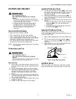
Lighting the Pilot Burner Flame

STOP: READ THE WARNINGS ABOVE.

The pilot burner flame must be lit manually. If the pilot burner 
flame has gone out, follow these instructions exactly.

1.

Set the thermostat to its lowest setting.

2.

Disconnect all electric power to the appliance.

3.

Remove the gas control access panel.

4.

Push in the gas control knob slightly and turn 
clockwise

 to OFF. 

NOTE: The gas control knob can not be turned from PILOT 

to OFF unless it is pushed in slightly. Do not force the 

gas control knob.

5.

Wait five minutes to clear out any unburned gas. If you 

then smell gas, STOP! Follow ÒBÓ in the Warnings 

above. If you do not smell gas, continue with the next step.

6.

Remove the pilot burner access panel located below 

and behind the gas control.

7.

Find the pilot burner by following the metal tube from 
the gas control. The pilot burner is between the two 

burner tubes behind the pilot burner access panel.

8.

Turn the gas control knob counterclockwise

to 

PILOT.

9.

Push and hold the gas control knob all the way in. 

Immediately light the pilot burner flame with a match 
and continue holding the gas control knob in for one 

minute after the pilot burner flame is lit. 

10.

Release the gas control knob and it will pop back up. 
The pilot burner flame should remain lit. If pilot burner 

flame goes out, repeat steps one through ten.

a. If the gas control knob does not pop up when 

released, stop immediately and call your service 

technician or gas supplier.

b. If the pilot flame will not stay lit after several tries, 

turn the gas control knob to OFF and call your 

service technician or gas supplier.

11.

Turn the gas control knob counterclockwise

 to ON.

12.

Replace the pilot burner access panel.

13.

Replace the gas control access panel.

14.

Reconnect all electric power to the appliance.

15.

Set the thermostat to the desired setting.

Turning Off the Appliance

Vacation Shutdown

Set the thermostat to the desired room temperature while you 

are away.

Complete Shutdown

Push the gas control knob in slightly and turn 
clockwise

to OFF. Do not force. Appliance will 

completely shut off. Follow the Lighting Procedures above to 

resume normal operation.

Summary of Contents for V8200

Page 1: ...ize Straight through body pattern right angle adapters available for inlet and outlet 1 2 inch inlet and 1 2 inch outlet adapters available for 3 8 or 3 4 inch inlet or outlet Adjustable servo regulator effectively maintains almost constant gas output pressure under wide fluctuations in gas supply pressure Factory setting does not need readjustment for specific rating of furnace Inlet and outlet s...

Page 2: ...0A7001 include an ECO connector Part No 394332 that has two 1 4 inch quick connect terminals Electrical Ratings Supply Voltage 24 Vac 60 Hz Power Unit Hold in current 300 mA maximum Drop out current 250 to 90 mA Thermocouple Nominal output 30 mV 0 018 ohms Open Circuit Turndown Voltage 2 mV Electrical Connections 1 4 inch male quick connects Two convenience terminals on top of control optional Ter...

Page 3: ...nge Kits include one flange with attached O ring four mounting screws 9 64 inch hex wrench and instruction sheet Pressure Rating AGA rating 1 2 psi 3 5 kPa inlet pressure Pressure Regulation See Table 1 Regulator adjustment accessible from top of gas control Mounting Can be mounted 0 to 90 degrees in any direction from the upright position of the manual gas control knob including vertically Temper...

Page 4: ...ce manufacturer s instructions if available otherwise use the instructions provided below Convert Between Natural and LP Gas WARNING Fire or Explosion Hazard Can cause serious injury death or property damage 1 Do not use a gas control set for natural gas on an LP gas system or a gas control set for LP gas on natural gas system 2 When making conversion main pilot burner orifices MUST be changed to ...

Page 5: ...s the overall length of the gas control Fig 4 Install flange to gas control Choose Gas Control Location Do not locate the gas control where it may be affected by steam cleaning high humidity dripping water corrosive chemicals dust or grease accumulation or excessive heat To ensure proper operation follow these guidelines 1 Locate gas control in a well ventilated area 2 Mount gas control high enoug...

Page 6: ...the connection 2 Square off and remove burrs from end of tubing 3 Unscrew compression fitting from the pilot outlet Fig 2 Slip the compression fitting over the tubing and slide out of the way NOTE When replacing a gas control cut off old compression fitting and replace with the new compression fitting provided on the gas control Never use the old compression fitting as it may not provide a gas tig...

Page 7: ...Never use pipe compound Tighten only 1 4 turn beyond finger tight to give good electrical continuity Do not overtighten Fig 9 Installing thermocouple and optional ECO connector to the power unit APPLY WRENCH FROM TOP OR BOTTOM OF GAS CONTROL TO EITHER SHADED AREA WHEN FLANGE IS NOT USED APPLY WRENCH TO FLANGE ONLY WHEN FLANGE IS USED M3079 GAS CONTROL TIGHTEN NUT ONE TURN BEYOND FINGER TIGHT FITTI...

Page 8: ... terminals on the ECO connector Table 5 Maximum Length of Supplementary Limit Leadwires when using Q340A Thermocouple Table 6 Maximum Length of Supplementary Limit Leadwires when using Q309A Thermocouple L1 HOT L2 1 24V THERMOSTAT OPTIONAL CONVENIENCE TERMINALS TH TR TH TR GAS CONTROL TERMINALS HIGH LIMIT CONTROLLER POWER SUPPLY PROVIDE DISCONNECT MEANS AND OVERLOAD PROTECTION AS REQUIRED DO NOT J...

Page 9: ...which could cause flashback in the appliance vestibule Light the main burner 4 With the main burner in operation paint all pipe joints including adapters and gas control inlet and outlet with rich soap and water solution 5 If a gas leak is detected tighten adapter screws joints and pipe connections 6 Replace the part if gas leak can not be stopped Light the Pilot Burner Flame 1 Turn the gas contro...

Page 10: ...e pressure regulator adjustment cap and screw b Using a screwdriver turn the inner adjustment screw clockwise to increase or counterclockwise to decrease the main burner gas pressure c Always replace the cap screw and tighten firmly to ensure proper operation 4 If the desired outlet gas pressure or gas flow rate cannot be achieved by adjusting the gas control check the gas control inlet pressure u...

Page 11: ...em The maintenance program should include regular checkout of the gas control as outlined under Startup and Checkout and the control system as described in the appliance manufacturer s literature Maintenance frequency must be determined individually for each application Some considerations are Cycling frequency Appliances that may cycle 100 000 times annually should be checked monthly Intermittent...

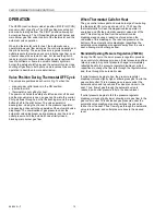
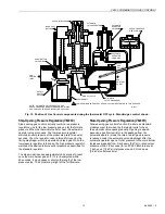
Page 12: ... valve diaphragm spring pressure and the lack of outlet pressure hold the automatic valve firmly closed blocking main burner gas flow When Thermostat Calls for Heat The gas control allows pilot and main burner gas flow during the thermostat ON cycle as shown in Fig 13 When the thermostat calls for heat the magnetic valve operator is energized and lifts the automatic operator valve disc off its sea...

Page 13: ...er may relight at the full flow rate Slow Opening Pressure Regulation V8200H Slow opening gas controls function the same as standard models except that when the thermostat calls for heat the automatic valve opens gradually Opening is slowed because a gas flow restrictor in the passage from the automatic operator slows the rate at which gas pressure is reduced under the automatic valve diaphragm af...

Page 14: ... thermocouple current drops and the power unit drops out closing the safety shutoff valve When pilot flame goes out When pilot flame goes out or is too small to reliably light the main burner thermocouple output drops below the power unit hold in value The power unit drops out closing the safety valve and stopping all gas flow through the control With the loss of outlet pressure the automatic valv...

Page 15: ...istance If above 11 ohms replace the gas control If the Main Burner Will Not Come On With a Call for Heat 1 Ensure the gas control knob is in the ON position 2 Adjust the thermostat several degrees above room temperature 3 Use an ac voltmeter to measure the voltage across terminals TH and TR If a No voltage is present check the control circuit for proper operation b 24 Vac is present but first ope...

Page 16: ... continue with the next step 6 Remove the pilot burner access panel located below and behind the gas control 7 Find the pilot burner by following the metal tube from the gas control The pilot burner is between the two burner tubes behind the pilot burner access panel 8 Turn the gas control knob counterclockwise to PILOT 9 Push and hold the gas control knob all the way in Immediately light the pilo...

Reviews: