background image

V9055A,D MODULATING FLUID POWER GAS VALVE ACTUATOR

3

60-2311-11

Damper Arm Rating (damper drives one direction only):

Standard Models: 20 lb. maximum at 2-11/16 in. radius at 20°F 

to 125°F and 5 lb at -40°F to 20°F (9 kg maximum at 68 mm 

radius at -7°C to 66°C and 2.3 kg at -40°C to -7°C).

Model with Damper Shaft Return Spring: 10 lb maximum at 

2-11/16 in. radius at 20°F to 125°F and 5 lb at -40°F to 20°F 

(4.5 kg at 68 mm radius at -7°C to 66°C and 2.3 kg at -40°C 

to -7°C).

Damper Shaft:  Shaft is 3/8 in. (9.5 mm) for use with 7616BR 

Damper Arm. Models available with damper shaft return 

spring.

Ambient Temperature Rating:

-40°F to 125°F (-40°C to 52°C) for 60 Hz models, and 

-10°F to 125°F (-23°C to 52°C) for 50 Hz and 50/60 Hz models.

Mounting Means:  Actuator attaches directly to valve with two 

setscrews. Valve and actuator can be mounted in any position.

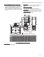
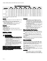
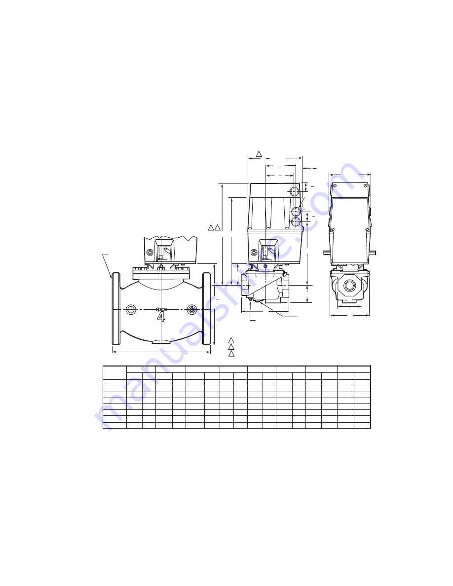
Installation Dimensions: See Fig. 1.

Fig. 1. V9055/V5055 dimensions in inches. (mm).

NEMA 4 Enclosure:  Model available.

B

E

F

C

D

A

G

3

1

D

1/4 INCH NPT
DOWNSTREAM TAP 
AND PLUG

1/4 INCH NPT
UPSTREAM TAP 
AND PLUG (1/4 BSP
ON INTERNATIONAL 
MODELS)

2

1
2

3

 [32.5]

KNOCKOUT

FOR1/2 INCH

CONDUIT (4)

OCTAGON

3/4 [19.1] BOLT

HOLES (8)

ON 3-3/4 (95)

RADIUS

1 9

32

1

3

16 [30]

9

3

16

[233]

27

32 [21.5]

3 23

32

5

[94.5]

[127.0]

3 19

32 [91]

6 3

4

[171.5]

3/4
1
1-1/4
1-1/2
2
2-1/2
3
4

VALVE SIZE

INCH

11-1/8
11-1/8
11-1/8
11-1/8
11-1/4
11-3/4
11-3/4
14-1/8

2-3/4
2-3/4
2-3/4
2-3/4
2-7/8
3-3/8
3-3/8
5-13/16

  8-3/16
  8-3/16
  8-3/16
  8-3/16
  8-5/16
  8-13/16
  8-13/16
11-7/32

5-3/4
5-3/4
5-3/4
5-3/4
8-3/8
9-1/4
9-1/4

12-1/2

13-1/8
13-1/8
13-1/8
13-1/8
13-1/4
13-3/4
13-3/4
16-3/16

2-13/16
2-13/16
2-13/16
2-13/16
3-1/2
4-1/2
4-1/2
    —

333.4
333.4
333.4
333.4
336.5
349.3
349.3
411.0


DIM A

IN.

MM

DIM B

IN.

MM

DIM C

IN.

MM

DIM D

IN.

MM

DIM E

IN.

MM

DIM F

IN.

MM

DIM G

OCTAGON

IN.

IN.

MM

MM

ALLOW 4 INCHES CLEARANCE FOR ACTUATOR REMOVAL.
ADD 1/8 INCH TO DIMENSION FOR MODELS WITH NEMA 4 ENCLOSURE.
ADD 1/4 INCH TO DIMENSION A FOR MODELS WITH NEMA 4 ENCLOSURE.

M7321

282.6
282.6
282.6
282.6
285.8
298.5
298.5
358.8

69.9
69.9
69.9
69.9
73.0
85.7
85.7

147.6

208.0
208.0
208.0
208.0
211.1
223.8
223.8
285.0

146.1
146.1
146.1
146.1
212.7
235.0
235.0
317.5

2-1/4
2-1/4
2-1/4
2-1/4
2-3/4
2-3/4
2-3/4
4-5/8

57.2
57.2
57.2
57.2
69.9
69.9
69.9

117.5

4-13/16
4-13/16
4-13/16
4-13/16
7-19/32
7-19/32
7-19/32

122.2
122.2
122.2
122.2
192.9
192.9
192.9

71.4
71.4
71.4
71.4
88.9

114.3
114.3

— 

Summary of Contents for V9055A

Page 1: ...e for 60 Hz models is 40 F to 125 F 40 C to 53 C Ambient temperature range for 50 Hz and 50 60 Hz models is 10 F to 125 F 23 C to 52 C Auxiliary 1 2 hp rated switch is available for field installation Integral damper shaft provides a maximum of 20 lb 9 kg of force Valve and actuator may be mounted in any position Model is available with NEMA 4 IP54 weatherproof enclosure V9055D V5055C E and V9055D...

Page 2: ...capacity curves Table 1 Pressure Ratings of Actuator Valve Combinations a Max Operating Pressure Differential UL or Max Operating Pressure CSA maximum allowable pressure drop from inlet to outlet for proper operation b Max rated pressure UL or Max Close off Pressure CSA maximum pressure that the valve can be exposed to without leak age or damage to the valve c Applies for small body V5097 valves 3...

Page 3: ... 3 32 5 KNOCKOUT FOR1 2 INCH CONDUIT 4 OCTAGON 3 4 19 1 BOLT HOLES 8 ON 3 3 4 95 RADIUS 1 9 32 1 3 16 30 9 3 16 233 27 32 21 5 3 23 32 5 94 5 127 0 3 19 32 91 6 3 4 171 5 3 4 1 1 1 4 1 1 2 2 2 1 2 3 4 VALVE SIZE INCH 11 1 8 11 1 8 11 1 8 11 1 8 11 1 4 11 3 4 11 3 4 14 1 8 2 3 4 2 3 4 2 3 4 2 3 4 2 7 8 3 3 8 3 3 8 5 13 16 8 3 16 8 3 16 8 3 16 8 3 16 8 5 16 8 13 16 8 13 16 11 7 32 5 3 4 5 3 4 5 3 4 ...

Page 4: ...ide down if water is likely to drip on it In this position water can become trapped in the electronics compartment When Installing This Product 1 Read these instructions carefully Failure to follow them could damage the product or cause a hazardous condi tion 2 Check the ratings given in the instruction and on the product to make sure the product is suitable for your application 3 Installer must b...

Page 5: ...er crank arm is used with a NEMA 4 actuator that is exposed to ice or sleet a suitable shield must be installed to prevent ice or sleet buildup The crank arm provides a maximum travel of 2 5 16 in 59 mm For complete installation information refer to the instructions packed with the 7616BR Crank Arm Fig 2 Crank Arm Operation Fig 3 Internal components and connections in V9055 WIRING WARNING Electric...

Page 6: ...n Verify proper operation after servicing ADJUSTMENTS IMPORTANT When using the V9055D with the V5055 V5097C or E two seals Valves match low fire minimum adjust ment to the burner and the application Too low of an adjustment could result in loss of burner flame Also plan to check this low fire adjustment at periodic maintenance intervals Adjust Low Fire Setting The low fire setting is adjustable fr...

Page 7: ...al potentiometer color to color to terminals W R and B on the actuator With the valve energized use the potentiometer to open and close the actuator It should run from the low fire position and to the fully open position If the actuator fails to operate properly replace it 1 Turn off the gas supply at the manual shutoff valve located upstream from the valve s being serviced 2 Shut off all electric...

Page 8: ...ssembly 13 Re attach the wires removed from the actuator termi nals and turn on the electrical power 14 With the gas still off cycle the actuator to check for proper mechanical operation CAUTION Be sure to perform a bonnet seal and seat leak check after installation Be sure to read and follow all instructions that come with the actuators valves seal and bonnet kits Each replacement assembly contai...

Reviews: