background image

Installation Instruction VARIODYN

®

 D1 System 


48 

FB 798663.GB0 / 05.19


 Control contacts (inputs/outputs)


The 48 control contacts (digital I/O) can be used for controlling voice alarm system components or for 
connection to other systems, such as a fire alarm control panel. The function of the input or output can be 
individually programmed in the configuration for each control contact.  

The reference potential for the control contacts is available at the four GND terminals.  

Contacts 41 – 48 are also suitable for monitoring the connected line for short-circuit or line interruption. 


Cable for cabinet rear panel UIM (Part No. 583401.21 - (Option) 

Prefabricated cabling from the control contacts to the cabinet rear panel; 
per UIM max. 1 piece. 

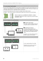
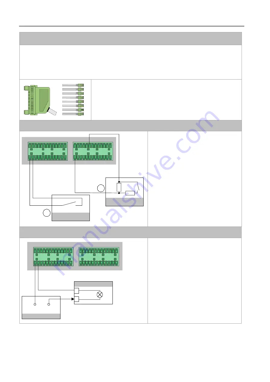
Connection diagram of the inputs (example) 

DIG

IT

AL

 I/O

DIG

IT

AL

 I/O

GND 1 2 3 4 5 6 7 8 9 10 11 12

GND

GND

GND

13 14 15 16 17 18 19 20 21 22 23 24

25 26 27 28 29 30 31 32

34 35 36

37 38 39 40 41 42 43 44 45 46 47 48

33

R1

R2

3

K3

680

1

2

ext. device without

monitoring

ext. device with

End-of-Line monitoring


 Input with switch contact 

The input is switched to GND and tripped by 
closing the external, potential-free contact.  


 Input with line monitoring 

The "line monitoring" function can be 
activated in the configuration for the control 
outputs 41 to 48. In this case, the connected 
line is monitored for wire break and short-
circuit. 
 
Connection to external monitoring resistors 
(R1/R2) is required for this function.  

Connection diagram of the outputs 

DIG

IT

AL

 I/O

DIG

IT

AL

 I/O

GND 1 2 3 4 5 6 7 8 9 10 11 12

GND

GND

GND

13 14 15 16 17 18 19 20 21 22 23 24

25 26 27 28 29 30 31 32

34 35 36

37 38 39 40 41 42 43 44 45 46 47 48

33

ext. device

+

0 V / GND

+ U

B

power supply


An active output switches to 0V / GND.  
 
Triggering of an ext. device (+24 V DC) 
current consumption max. 50 mA 


Summary of Contents for VARIODYN D1

Page 1: ...VARIODYN D1 System GB Installation Instruction 798663 GB0 05 2019 ...

Page 2: ...n their operation as included in this manual trained installation or service personnel with the necessary qualification for carrying out repairs on fire alarm and extinguishing systems or who are authorised to operate ground and label electrical circuits and or safety equipment systems Symbols The following information is given in the interest of personal safety and to prevent damage to the produc...

Page 3: ...r 21 6 Devices 25 Digital Output Module DOM 25 View Control Module VCM 39 Main Switch Unit MSU 42 Universal Interface Module UIM 47 System Communication Unit SCU 52 7 Power Amplifiers PA 56 Power amplifier 2XH Series 57 Power amplifier 2XD Series 59 Connect 2XH and 2XD series 61 Power Amplifiers 4XD Series 63 Power Amplifier 4XV series 69 Connect 4XD and 4XV series 70 Using backup amplifiers 72 8 ...

Page 4: ... who are dependent on external help in an emergency e g when evacuation of the building is necessary This may include people who are ill the elderly and children The voice alarm system is mainly used in combination with a fire alarm control panel FACP for emitting alarms In practice the voice alarm system is also used for purposes outside of this area of application Typical examples of this includ...

Page 5: ...nded for qualified technicians or trained installers and contain all of the important information needed for assembling and installing VARIODYN systems Additional information on assembly operation commissioning and configuration can be found in the following documents Part No Name 798661 GB0 System design principles for Voice Alarm Systems VAS 798662 GB0 Operating Instructions for the VARIODYN D1 ...

Page 6: ...operly assembled Strong electrical electromagnetic and mechanical influences must be avoided This especially applies to the installation of components and installation cables in the direct vicinity of fluorescent lamps or energy cables and to mounting on vibrating unstable surfaces such as thin partition walls The system may not be installed in facilities or equipment that have damaging effects Pa...

Page 7: ...N 54 17 2006 Declaration of Performance DoP 20997130701 DoP 00376130701 DoP 00405140414 The DoP numbers apply to VARIODYN D1 voice alarm systems including all components The valid DoP numbers are specified on the type plates of the devices The standards and guidelines listed in this documentation apply in their respective latest versions ...

Page 8: ... devices Objective rating of speech intelligibility by speech transmission index DIN EN 50849 Sound systems for emergency purposes formerly 60849 DIN EN 61672 Electroacoustics Sound level meters DIN EN ISO 9921 Ergonomics Assessment of speech communication DIN VDE 0800 1 Telecommunications general concepts requirements and tests for the safety of facilities and apparatus DIN VDE 0815 Wiring cables...

Page 9: ...ents into a building specific configuration Special solutions can thus be implemented economically and effectively for buildings of different sizes and for various alarm purposes call station loudspeaker DOM PA1 PA2 Service PC laptop PA1 PA2 DOM LAN Ethernet LIM LIM LIM LIM ETCS VARIODYN D1 Comprio net EOL DOM PA1 PA2 UIM SCU CD player loudspeaker call station call station Loop Spur Spur amplifier...

Page 10: ...iagram are required for this purpose LAN 1 essernet 1 2 2 3 3 Fig 2 Redundancy of the VARIODYN D1 System ESSER fire alarm control panel FACP Serial essernet Interface TWI RS232 adapter Part No 583386 21 The technical performance characteristics may be limited by standards directives and local requirements For more information on the devices and accessories see documentation Part No 798683 GB0 7986...

Page 11: ...g on the amplifier used See tables in chapters 3 4 2 and 5 1 2 Up to 5 spurs with more than one loudspeaker per ring loop with EOL Do not route outbound and inbound rings conductors in the same cable or the same conduit A single loudspeaker output of a DOM may be loaded with the max channel amplification power of the connected amplifier In this case the other loudspeaker outputs of the same channe...

Page 12: ...e optic cables of type multimode 50 125 µm GI 62 5 125 µm GI with duplex SC connection are required If E30 cabling is required the cable type JE H St H 4 x 2 x 0 8 mm BETAflam must always be used Max length 150 m PIN1 PIN8 PIN Assignment DOM DCS DCSF 1 RX TX 2 RX TX 3 GND GND 4 TX RX 5 TX RX 6 GND GND 7 24 V DC 24 V DC 8 24 V DC 24 V DC Fig 3 DAL bus RJ45 connector blue The RX and TX connections i...

Page 13: ...gned Fig 4 Ethernet RJ45 connector yellow AVC Inputs Automatic Volume Control Microphones are connected to the AVC inputs via a microphone cable e g 2 x 0 5 mm shielding in order to regulate the volume based on the ambient noises Attach the cable shielding of the microphone cable to the connector plug PIN1 PIN8 PIN Assignment 1 Not assigned 2 Not assigned 3 Not assigned 4 Not assigned 5 Not assign...

Page 14: ...Cable for rear cabinet wall DOM4 24 for loudspeaker connection Ex works cabling of the loudspeaker speaker SPK outputs of the DOM4 24 to the rear cabinet wall up to 4 cables are required per DOM4 24 583452 21 Input cable DOM XV VARIODYN D1 Ex works cabling of DOM 1 to final amplifier 1 2 channels audio frequency AF control 583471 21 Output cable XV DOM VARIODYN D1 Ex works cabling from final ampli...

Page 15: ...ple If a different comparable cable type is used please bear in mind the output and cable length required Conversion Cable cross section Cable diameter 0 5 mm 0 8 mm 0 75 mm 1 0 mm Calculation aid Loop fault free Max 1 dB 10 power loss Loop with faults Additional 2 dB power loss Up to 1st speaker max 150 m cable length the further speakers are evenly distributed 3 4 3 Specification Loop Isolator M...

Page 16: ...ombination of a DOM and two power amplifiers Max two double final amplifiers may be installed one above the other The lower power amplifier is also screwed on with a installation bracket A ventilation panel Part No 583708 is installed beneath this and a DOM is installed above the amplifier combination This results in a 6 HU combination and the power amplifiers can always be connected with the syst...

Page 17: ...RIODYN system components example Abbreviation Description Part No UIM Universal Interface Module 583331 21 MSU Main Switch Unit 583371 21 SCU System Communication Unit 583381 22 583381 31 VCM View Control Module 583315 DOM Digital Output Module 583361 22 583362 22 PA Power Amplifier 580221 41 580222 41 580231 580232 580242 580243 580248 580248 11 580249 11 580262 ...

Page 18: ...d UPS was taken into account Despite the high stability the cabinet system has a low deadweight which simplifies transport and assembly work The VARIODYN cabinet systems are available in different heights and designs see Product Catalog 1 HU 1 height unit 44 45 mm or 1 inches 6HU 6HU 6HU 6HU 6 24 18 12 1 2 3 4 5 6 7 8 9 10 11 12 13 14 15 16 17 18 19 20 21 22 23 24 25 26 27 28 29 30 31 32 33 34 35 ...

Page 19: ...w Control Module VCM approx 0 9 Kg Main Switch Unit MSU approx 4 2 Kg Universal Interface Module UIM approx 3 6 Kg System Communication Unit SCU approx 3 Kg Ventilation field Ventilation field 6HU 5HU DOM PA1 PA2 UIM SCU MSU VCM Fig 9 Sample arrangement of the devices As a rule in a cabinet the heavy devices should be installed on the bottom and the lighter components should be installed towards t...

Page 20: ...s must be closed with suitable material Open installation spaces in the pivot frame and or installation cabinet must be closed with filler plates Fibre optic converter Special fibre optic converters are required to connect the digital call station DCS or the interface module UIM to a DOM 4 xx via fibre optic cables see Accessories The fibre optic cable connection increases the possible distance ca...

Page 21: ...pur line incl EOL DOM EOL black red white Fig 12 Wiring of loudspeaker incl EOL and volume controller EOL black red white Up to 250 W inclusive EOL black red white As of 250 W or with volume controller Volume controller Part No 581321 581322 581323 The loudspeakers can be connected using communications cable I Y St Y n x 2 x 0 8 mm or comparable for example If a different comparable cable type is ...

Page 22: ...rcuit relay Each circuit is constantly monitored for short circuit earth fault and interruption Either standard loudspeaker circuits or a loop line can be connected to the connection terminals of the loudspeaker outputs A loop takes up the connection terminals for two standard loudspeaker circuits outbound and inbound connection of the loop DOM DOM Ringleitungstechnik Loop technology EOL A LIM B L...

Page 23: ...ed in parallel to increase the cable cross section Do not route outbound and inbound loop conductors in the same cable or the same conduit Amplifier Maximum number of LIMs Max loop length including spur lines 2XD250 40 1000 2XD400 64 1000 4XD250B 25 500 4XD300 40 1000 4XD500 50 1000 No other amplifiers are approved for combination with LIMs Observe the maximum number of LIMs and the loop length fo...

Page 24: ...e cable or the same conduit Maximum ring loop length 1000 m including connected spur lines observe cable cross section Install LIM at the start and end of the loop Maximum distance to DOM 10 m For performance calculation use 3 watts per LIM Twisted loudspeaker cable 2 x 1 5 mm or communication cable I Y St Y n x 2 x 0 8 mm can be used for the loop Note the building specific power requirements and ...

Page 25: ...al voltage via IEC power socket Device fuses F1 and F2 Two wire interface TWI e g for connection of a time synchronisation module TCM 3 1 Do not connect 2 x RJ45 plug connections AF output to power amplifier PA AVC1 to AVC4 4 x inputs for automatic volume control AVC Connection terminals of the eight potential free control contacts switching capacity max 30 V AC 1 A or 30 V DC 1 A Plug connection ...

Page 26: ...M a service PC or an fire alarm control panel Do not connect second jack A TWI RS232 adapter Part No 583386 21 is also required for connecting the service PC and the FACP PA CH1 2 and PA CH3 4 output to power amplifier PA CH 1 2 PA CH 3 4 0 dB signal output for connection to a power amplifier PA Power amplifier PA Connection PIN Assignment of RJ45 socket for connection to a DOM D1 LINK CONTROL INT...

Page 27: ...r external devices e g CD player etc 8 potential free control contacts CONTACTS 1 2 5 6 3 4 7 8 The potential free control contacts can be used to control external devices or perform switching operations e g activation of emergency call points fire alarm systems and telephone exchanges with the control contacts NO NC contacts Max switched load 30 V AC 1 A or 30 V DC 1 A The function of the control...

Page 28: ...nals of the DOM and run from there internally to the individual loudspeaker circuits use only system cables Backup amplifiers are also connected using specific backup cables see product group catalogue Max cable cross section 1 5 mm Connection example amplifier REP PA 1 2 1 2 3 4 3 4 OUTPUT CH1 CH2 NC PA DOM OUTPUT CH1 CH2 NC PA Output cable Part No 583477 21 REP PA 1 2 1 2 3 4 3 4 OUTPUT CH1 CH2 ...

Page 29: ...fabricated cabling of the SPK outputs of the DOM4 8 to the cabinet rear panel One cable per DOM4 8 or up to four cables per DOM4 24 can be connected Also suitable for cabling DOM4 x switch contacts to the rear cabinet wall Cable for DOM4 8 Part No 583451 21 Cable for DOM4 24 Part No 583452 21 Reset button DAL4 Do not press button for factory testing only DAL1 to DAL4 Digital Audio Links of the DOM...

Page 30: ...y Fig 20 Location of the battery with open housing A 3 V lithium battery type CR2430 is integrated into the DOM unit to protect the customer data In order to ensure the protection over the long term this battery should be replaced after no more than five years such as during regular maintenance To do this save the customer data to the service PC switch off the power supply mains and battery carefu...

Page 31: ... 1 in the frequency range Signal to noise ratio at nominal level 65 dB A weighted 60 dB unweighted Input impedance typ 200 Ω 8 control contacts Contact type relay contact potential free Max voltage 30 V AC 1 A or 30 V DC 1 A Max current 5 A constant current Impulse withstand voltage Min 1 5 kV Pass through contacts Audio Max voltage 250 V AC 5 A or 30 V DC 5 A Impulse withstand voltage min 1 5 kV ...

Page 32: ... installed according to their output so that each amplifier channel operates with the ideal number of loudspeaker lines This simply requires the use of relevant amplifier output cables and in the case of application 1 24 a connection board Description Part No Figure Connection Board 583369 Output cable1 18 1 channel up to 6 lines 1 channel up to 18 lines 583430 Output cable 2 12 2 channels each up...

Page 33: ...er lines When using a four channel amplifier an extra DOM and the application 2 12 can use the remaining two channels Fig 21 Overview application 2 12 DOM 2 PA CH 1 2 CH 3 4 DOM 1 1 1 2 2 Fig 22 Input output connection Example with 4XD125B Input cable DOM amplifier 0 5 m green audio frequency AF control to power amplifier PA 583491 or 583491A Output cable 2 12 2 channels each up to 12 lines 583431...

Page 34: ...ies six loudspeaker lines and can be used with amplifiers 4XD125B and 4XD250B for backup The two other channels can be used with application 2 12 for example Fig 23 Overview application 2 18 DOM 2 PA CH 1 2 CH 3 4 DOM 1 1 1 2 2 Fig 24 Input output connection Example with 4XD125B Input cable DOM amplifier 0 5 m green audio frequency AF control to power amplifier PA 583491 or 583491A Output cable1 1...

Page 35: ... 2 is solely permitted with amplifiers 4XD125B and or 4XD250B The spare connections on the connection board must not be used to connect additional amplifiers Fig 25 Overview application 1 24 Variant 1 PA DOM 2 DOM 3 DOM 1 Connection Board 583369 1 1 2 3 4 1 Fig 26 Input output connection Input cable DOM amplifier 0 5 m green audio frequency AF control to power amplifier PA 583491 or 583491A Output...

Page 36: ...mplifier channel supplies all the loudspeaker lines of the DOM a total of 96 zones No backup Fig 27 Overview application 1 24 Variant 2 PA DOM 2 DOM 3 DOM 1 DOM 4 Connection Board 583369 1 3 1 1 3 Fig 28 Input output connection Input cable DOM amplifier 0 5 m green audio frequency AF control to power amplifier PA 583491 or 583491A Output cable 1 24 2 channels each up to 24 lines 583432 ...

Page 37: ...ker lines of the DOM separated according to A and B 96 AB zones No backup Fig 29 Overview application 1 24 Variant 3 PA DOM 2 DOM 3 DOM 1 DOM 4 Connection Board 583369 1 3 1 1 3 PA DOM 2 DOM 3 DOM 1 DOM 4 Connection Board 583369 1 3 1 1 3 Fig 30 Input output connection Input cable DOM amplifier 0 5 m green audio frequency AF control to power amplifier PA 583491 or 583491A Output cable 1 24 2 chann...

Page 38: ...plication 1 24 Variant 3 PA DOM 1 DOM 2 Connection Board 583369 3 1 1 PA DOM 1 DOM 2 Connection Board 583369 3 1 1 Fig 32 Input output connection The spare connections on the connection board must not be used to connect additional amplifiers Input cable DOM amplifier 0 5 m green audio frequency AF control to power amplifier PA 583491 or 583491A Output cable 1 24 2 channels each up to 24 lines 5834...

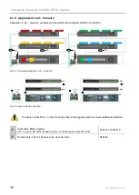
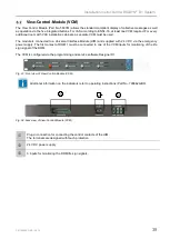
Page 39: ...Module UIM and supplied with 24 V DC via the emergency power supply The first contact of DOM 1 must be connected to one of the VCM inputs for monitoring of the life sign signal of the DOM The VCM is configured via the programming and service software Designer D1 Fig 33 Front view of View Control Module VCM Additional information on the indicators refer to operating instructions Part No 798662 GB0 ...

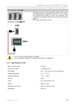
Page 40: ...2 34 35 36 37 38 39 40 41 42 43 44 45 46 47 48 33 VCM UIM For the connection diagram of the UIM inputs outputs see chapter 6 4 24 V DC power supply 24 V The supply of 24 V DC to the VCM takes place via the 24 V DC emergency power supply Use cable type I Y St Y 2 x 2 x 0 8 mm and the enclosed two pin plug to make the connection Max cable cross section 1 5 mm Connection example 24 V DC to 24 V DC ba...

Page 41: ... of the life sign signals Max cable cross section 1 5 mm Connection example DOM DOM 1 CONTACTS 1 2 5 6 3 4 7 8 VCM DOM 1 Do not connect terminals DOM 2 and DOM 3 For the connection diagram of the DOM inputs outputs see chapter 6 1 6 2 1 Specification VCM Back up power supply 24 V DC Power consumption 10 mA 24 V DC Air Humidity 40 90 rel hum non condensing Ambient temperature 5 C 55 C Storage tempe...

Page 42: ...ctor PE and neutral conductor N must always be connected Up to 4 components can be connected to terminals 2 3 and 4 in accordance with the requirements These terminals can be single switched as a single pole with the fuses arranged on the front Potential free switch contacts for activating external devices for the remote display of the switching status of the corresponding overcurrent circuit brea...

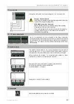
Page 43: ...ch phase is protected by a separate overcurrent circuit breaker The front side IEC power socket is also supplied via phase 1 L1 All 3 phases can be switched individually via the front side switches Switch contacts AUX L1 CONTACTS AUX L2 AUX L3 max 250V 4A The switch contacts AUX L1 L2 L3 are assigned to the overcurrent circuit breakers L1 L2 L3 on the front side Each switch contact is activated wh...

Page 44: ...erminal block of the MSU for each amplifier and to the IEC power socket of the respective amplifier 4 Use a CAT5 patch cable yellow to connect the ETHERNET connection of the MSU and of the DOM 5 If a second amplifier PA is present it must be connected to the free terminal block of the MSU and to the IEC power socket of the respective amplifier with another prefabricated power cord Ensure that the ...

Page 45: ...ltage phase failure asymmetry including for reverse voltage neutral conductor missing in the system neutral conductor break in the device supply cable neutral conductor mixed up with phase The control panels must only be connected to the mains by qualified electricians and in compliance with all relevant standards and guidelines MAINS max 3 x 18A L1 L2 L3 N PE L1 L2 L3 N 1 3 5 2 4 6 8 L1 L2 L3 N 1...

Page 46: ... 150 A Approvals Certifications VDE Semko EN 60934 240 V AC 28 V DC BV LroS 250 V AC 28 V DC UL CSA 250 V AC 50 V DC Auxiliary contacts Rated voltage 250 V AC Rated current max 4 A 250 V AC Withstand voltage Test voltage 3000 V AC Insulation resistance 100 MΩ 500 V DC General specifications Ambient temperature 5 C 55 C Storage temperature 10 C 60 C Humidity 15 90 rel hum non condensing Housing met...

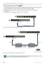
Page 47: ...g 40 Rear view of universal interface module UIM 48 control contacts individually programmable as input or output max cable cross section 1 5 mm Two analogue audio outputs OUTPUT 1 OUTPUT 2 XLR pin 1 Shielding XLR pin 2 Tone wire a XLR pin 3 Tone wire b Two analogue audio inputs INPUT 1 INPUT 2 Connection of the DAL bus Digital Output Module DOM Not used VARIODYN D1 to VARIODYN 3000 If the VARIODY...

Page 48: ... O GND 1 2 3 4 5 6 7 8 9 10 11 12 GND GND GND 13 14 15 16 17 18 19 20 21 22 23 24 25 26 27 28 29 30 31 32 34 35 36 37 38 39 40 41 42 43 44 45 46 47 48 33 R1 R2 3K3 680Ω 1 2 ext device without monitoring ext device with End of Line monitoring Input with switch contact The input is switched to GND and tripped by closing the external potential free contact Input with line monitoring The line monitori...

Page 49: ...n the L R CINCH sockets Audio inputs AUDIO INPUT 1 L R AUDIO INPUT 2 L R The two analogue potential free audio inputs can be used e g to connect an external audio source CD MP3 player etc and are arranged symmetrically on the XLR sockets and asymmetrically on the CINCH sockets The stereo signal is mixed into a mono signal on the CINCH sockets The XLR socket and corresponding CINCH sockets cannot b...

Page 50: ... the CINCH or XLR sockets of the UIM and 4 XLR socket Pin 1 shielding pin 2 tone wire A pin 3 tone wire B UIM DAL 1 4 DOM CAT5 max 300 m Fig 41 Connection of the UIM to the DOM using CAT5 cable DAL 1 4 DOM OIM DCS O max 10 m max 10 m UIM Fibre optics cable max 2000 m Multimode Power supply or via 24 V DC from system Part No 583316 21 Part No 583317 21 Fig 42 Connection of the UIM to the DOM via fi...

Page 51: ...potential free Input impedance 100 kΩ CINCH socket Type Asymmetrical potential free Input impedance 1 kΩ Control contacts Input contact Max input voltage max 24 V DC over DAL Bus Input voltage logical 0 8 5 V DC 5 6 kΩ Input voltage logical 1 7 5 V DC 4 5kΩ Input resistance 10 kΩ Output contact Max external voltage 24 V DC Load current per output max 50 mA Short circuit proof against 24 V 1 secoun...

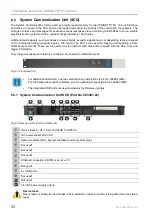
Page 52: ...ored on the internal hard disk and are saved with the date time and trigger information Only the power supply and network connection are needed to install the device Fig 43 Front view SCU For additional information see the commissioning instructions Part No 798664 GB0 For information about LED indicators see the operating manual Part No 798662 GB0 The integrated USB ports are used exclusively for ...

Page 53: ...ce fuse 5 AT 250 V IEC power socket 230 V AC incl device fuse 1 6 AT System restart button System shutdown button system stop Not used Not used Ethernet connection to DOM or service PC Not used Not used 4 x USB ports Not used 11 Not used 12 24 V DC power supply input Device fuses Never repair or bridge the device fuse that is installed or replace it with anything other than the stated type ...

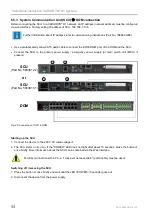
Page 54: ... the SCU to the primary power supply emergency power supply or main switch unit MSU if present SCU DOM 1 2 Part No 583381 22 SCU Part No 583381 31 1 2 or Fig 46 Connection of SCU to DOM Starting up the SCU 1 Connect the device to the 230 V AC rated voltage 2 The SCU starts on its own If the POWER LED does not light after about 10 seconds press the button once briefly More information about the SCU...

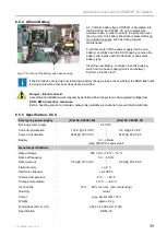
Page 55: ...e BIOS flash disk is being booted No other boot devices are permitted Danger Electric shock Assembly and installation work may only be performed when the system is de energised voltage free ESD EMC preventive measures Before handling electronic modules always take suitable precautions to prevent static electricity 6 5 5 Specification SCU Emergency power supply Part No 583381 22 Part No 583381 31 B...

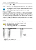
Page 56: ...hen operated under load Generous amplifier dimensioning provides for expansion options if the voice alarm system needs to be expanded at a later date e g due to changed use apportionment of the alarm areas Ventilation Temperature controlled forced ventilation ensures that the temperature stays low and remains even In the case of cabinet installation make sure there is sufficient ventilation incomi...

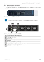
Page 57: ...mplifier Example 2XH500 Additional information on LED indicators refer to operating instruction Part No 798662 GB0 1 2 3 4 5 6 7 Fig 49 Rear view of power amplifiers Example 2XH500 230 V AC rated voltage via IEC power socket Primary fuse T 8 A 250 V On off switch DIP Switch Plug connection to DOM use system cable The SPK outputs are designed with touch protected terminals Plug connection AF input ...

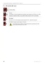
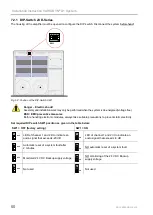
Page 58: ...icating the audio signals as of 20 dB or as of 6 dB Separate individual settings are possible for both channels 1 CH 1 and 2 CH 2 3 ON OFF DC FAULT ON An error in the emergency power supply 24 V DC if present is reported 3 ON OFF OFF No emergency power supply is connected If an emergency power supply is connected there will be no indication of a fault even though the DIP switch is set to OFF ...

Page 59: ...n on LED indicators refer to operating instruction Part No 798662 GB0 1 2 3 4 5 6 7 8 6 Fig 51 Rear view of power amplifiers Example 2XD250 230 V AC rated voltage via IEC power socket 24 V DC emergency power supply if available 0 V connection and housing Plug connection to DOM use system cable The SPK outputs are designed with touch protected terminals Configuration of the amplifier power 0 dB max...

Page 60: ...reventive measures Before handling electronic modules always take suitable precautions to prevent static electricity Set required DIP switch SW1 position as given in the table below SW1 OFF factory setting SW1 ON OFF 1 LED of channel 1 and 2 lit to indicate an audio signal that exceeds 20 dB ON 1 LED of channel 1 and 2 lit to indicate an audio signal that exceeds 6 dB OFF 2 Automatic reset of a sy...

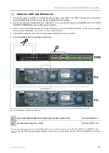
Page 61: ...onnect the SPK OUTPUT on the power amplifier and PA input of the DOM be sure to use the correct socket 4 The amplifier must be connected to a programmed DOM for correct operation 5 Connect additional power amplifiers accordingly 2 1 PA DOM PA Fig 53 Connection of the inputs outputs Input cable DOM amplifier AF output signal to power amplifier PA Part No 583491A 5 Output cable 2 amplifier DOM Part ...

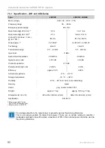
Page 62: ... dB 90 dB Channel separation 75 dB Distortion factor 1 kHz 0 05 0 3 Efficiency approx 50 80 Ambient temperature 5 C 55 C Storage temperature 10 C 60 C Humidity 40 90 rel hum non condensing Housing metal Colour grey similar to RAL 7016 Weight approx 17 kg approx 16 5 kg 19 kg Dimensions W x H x D 483 x 88 x 382 mm 2 HU 483 x 88 x 402 mm 2 HU Specification EN 54 16 6 Rated current 33 load 7 Acc EN 5...

Page 63: ...w of power amplifier 4XD125B Additional information on LED indicators refer to operating instruction Part No 798662 GB0 1 2 3 4 5 6 7 8 9 10 Fig 55 Rear view of power amplifier 4XD125 230 V AC rated voltage via IEC power socket and primary fuse T 8 A 250 V 24 V DC emergency power supply Plug connections to control unit use system cable The SPK outputs are designed with touch protected terminals 2 ...

Page 64: ...upply 4 ON 1 8 2 3 4 5 6 7 OFF Monitoring of the connected batteries activated factory setting ON No monitoring of the connected batteries required if no batteries are connected 5 ON 1 8 2 3 4 5 6 7 OFF Display of the audio signal strength via the two green LED High Low channel on the front side of the amplifier in the range 20 dB low and 6 dB high Display function for the deviation from the nomin...

Page 65: ...up to 105 Ah in compliance with standards Fig 56 Front view of power amplifier 4XD250B Additional information on LED indicators refer to operating instruction Part No 798662 GB0 1 2 3 4 5 7 6 8 9 Fig 57 Rear view of power amplifier 4XD250B 230 V AC rated voltage via IEC power socket and primary fuse T 8 A 250 V 24 V DC emergency power supply Plug connections to control unit use system cable The SP...

Page 66: ...pply via an external power supply 4 ON 1 8 2 3 4 5 6 7 OFF Monitoring of the connected batteries activated factory setting ON No monitoring of the connected batteries required if no batteries are connected 5 ON 1 8 2 3 4 5 6 7 OFF Display of the audio signal strength via the two green LED High Low channel on the front side of the amplifier in the range 20 dB low and 6 dB high Display function for ...

Page 67: ...the amplifier is suitable for rack mounting and has 24 V emergency power supply provided via an emergency power manager Fig 58 Front view of power amplifier 4XD300 Fig 59 Front view of power amplifier 4XD500 Additional information on LED indicators refer to operating instruction Part No 798662 GB0 1 6 2 3 4 5 7 Fig 60 Rear view of power amplifier 4XD300 230 V AC rated voltage via IEC power socket ...

Page 68: ...nsitivity illuminates from 6 dB for each channel CH 1 4 ON 1 2 3 4 5 6 OFF 20 dB CH 1 2 3 4 DC FAULT LOOP SHORT DETECT 6 dB ON Faults relating to the 24 V power supply AC and DC are displayed OFF Faults relating to the 230 V power supply AC only are displayed ON 1 2 3 4 5 6 OFF 20 dB CH 1 2 3 4 DC FAULT LOOP SHORT DETECT 6 dB ON Loop mode In the event of a short circuit the amplifier switches off ...

Page 69: ...logue 7 5 1 Power Amplifier 4XV300 4XV500 Fig 61 Front view of power amplifier 4XV300 Fig 62 Front view of power amplifier 4XV500 Additional information on LED indicators refer to operating instruction Part No 798662 GB0 1 2 3 4 5 Fig 63 Rear view of power amplifier 4XV300 4XV500 230 V AC rated voltage via IEC power socket Primary fuse F 8 A 250 V On off switch Plug connections to control unit use...

Page 70: ... Part No 583491A 3 Connect the SPK OUTPUT on the power amplifier and the IN PA input of the DOM using the amplifier DOM grey output cable Part No 583477 21 ensure that the correct slot is used as per the cable labelling Connect channels CH1 2 left slot and CH 3 4 right slot on the power amplifier 4XD125B as per the figure below DOM PA 2 1 CH 1 2 CH 3 4 2 Fig 64 Connection of the inputs outputs exa...

Page 71: ... noise ratio 90 dB A 97 dB A Channel separation 75 dB 83 dB Distortion factor 1 kHz 0 3 0 05 Efficiency 80 Ambient temperature 5 C 55 C Storage temperature 10 C 55 C Humidity up to 93 rel hum non condensing Housing Metal Colour grey similar to RAL 7016 Weight approx 9 kg approx 12 kg approx 14 3kg approx 14 4 kg approx 13 4kg approx 13 5 kg Dimensions w x h x d 483 x 44 x 400 mm 1HU 483 x 88 4 x 3...

Page 72: ...6 1 4 2 5 3 6 CH2 OUT CH3 OUT 1 4 2 5 3 6 1 4 2 5 3 6 CH4 OUT IN REP PA 1 2 1 2 3 4 3 4 DOM with main aplifiers DOM with backup amplifiers to additional DOM 1 2 The existing DOM can be used for the connection The second power amplifier replaces the first power amplifier With a two channel backup amplifier incl the backup cable RC 22 Part No 583422 21 up to 6 DOMs can be substituted This makes a ma...

Page 73: ...iers to additional DOM 1 2 One channel can act as backup for the other three channels With a four channel backup amplifier incl the backup cable RC 41 Part No 583441 up to five further DOMs can be replaced with 4XD125B and 4XD250B Use to connect the prefabricated cabling from one backup channel to three voice data channels for 3 1 backup in connection with four channel amplifier 4XD125B or 4XD250B...

Page 74: ...CH3 OUT 1 4 2 5 3 6 1 4 2 5 3 6 CH4 OUT IN REP PA 1 2 1 2 3 4 3 4 DOM with main aplifiers DOM with backup amplifiers to additional DOM 1 2 With a four channel backup amplifier incl the backup cable RC 44 Part No 583444 up to 6 DOMs can be substituted Use to connect the prefabricated cabling from four backup channels to four voice data channels Fig 67 Backup cable RC 44 VARIODYN D1 2 m Part No 5834...

Page 75: ... Fig 43 or via an MSU Fig 44 PA 230 V AC L1 N PE OR Fig 68 230 V AC direct connection example 230 V AC L1 N PE L2 MSU PA PA L3 Fig 69 230 V AC cabling via MSU example Danger Electric shock Assembly and installation work may only be performed when the system is de energised voltage free ESD EMC preventive measures Before handling electronic modules always take suitable precautions to prevent static...

Page 76: ...a mains power failure 230 V AC the connected batteries will supply the system with power without any interruption Fig 70 Front view Back up power supply Part No 581721 Mains fault Off Normal operation ON yellow Device switched off or no operating voltage Battery fault Off Normal operation ON yellow Error in one or more batteries Output ON green Normal operation Off Back up power supply output is f...

Page 77: ...nals for output contact Terminals for max six Power Amplifiers 24 V 40 A Temperature sensor Terminals for Battery connection terminals for output contact DIGITAL I O DIGITAL I O GND 1 2 3 4 5 6 7 8 9 10 11 12 GND GND GND 13 14 15 16 17 18 19 20 21 22 23 24 25 26 27 28 29 30 31 32 34 35 36 37 38 39 40 41 42 43 44 45 46 47 48 33 Output contacts NC NO Mains fault Batterie fault Output fault NC NO NC ...

Page 78: ... disconnector Part No 583716 PSU Fig 72 Connection example Danger Electric shock Assembly and installation work may only be performed when the system is de energised voltage free The installation kit fuse switch disconnector Part No 583716 can be used to switch off the emergency power supply batteries completely 24 V DC A standard fused conductor 150 A must be used for the connection to the positi...

Page 79: ...ted batteries will supply the system with power without any interruption Fig 73 Front view Back up power supply Part No 581722 24 Display The main control parameters Mains fault Off Normal operation ON yellow Device switched off or no operating voltage Battery fault Off Normal operation ON yellow Error in one or more batteries Output Off Normal operation ON green Charging Flashing Fast charge Faul...

Page 80: ...xternal error messages EXT FLT1 EXT FEHL 1 and EXT FLT2 EXT FEHL 2 Three output contacts Mains fault NETZFEHL BAT fault BATTFEHL and Gen fault SUMMFEHL Output contact connectors or terminals 3 pin sockets are provided for the output contacts 3 pin plugs are included with the delivery If these are plugged into the socket accordingly they can be used as normally open or normally closed contacts of t...

Page 81: ...ted batteries will supply the system with power without any interruption Fig 75 Front view Back up power supply Part No 581723 25 Display The main control parameters Mains fault Off Normal operation ON yellow Device switched off or no operating voltage Battery fault Off Normal operation ON yellow Error in one or more batteries Output Off Normal operation ON green Charging Flashing Fast charge Faul...

Page 82: ...EXT FEHL 1 and EXT FLT2 EXT FEHL 2 Three output contacts Mains fault NETZFEHL BAT fault BATTFEHL and Gen fault SUMMFEHL Connecting terminals for temperature sensor Output contact connectors or terminals 3 pin sockets are provided for the output contacts 3 pin plugs are included with the delivery If these are plugged into the socket accordingly they can be used as normally open or normally closed c...

Page 83: ... to one of these outputs The use of a separate fuse to protect each strand is recommended Connecting the batteries The power supply unit does not include dedicated fuses for the batteries If such fuses are required they should be installed close to the positive pole of a battery separately for each strand Use cable maximum diameter 16 mm2 to connect the batteries to the emergency power supply term...

Page 84: ...there must be no error messages pending in relation to the emergency power supply 1 The battery circuit resistance values cable cross sections for proper operation of the VA PA system depend on two factors Battery capacity Current consumption during an alarm 2 The factory configured resistance parameters can be changed during commissioning The software required for this is available online at www ...

Page 85: ...81723 25 Rated voltage 230 V AC Output voltage 24 V DC Output current idle max 12 A 16 A 2 A 32 A 4 A Battery charging current constant current for ext consumers Output current alarm max 150 A max 186 A max 372 A Weight 6 kg ca 5 2 kg ca 8 5 kg Dimensions W x H x D 483 x 88 x 395 mm 2 HU 483 x 45 x 328 mm 1 HU 483 x 90 x 328 mm 2 HU Specification EN 54 4 1997 A2 2006 EN 54 4 1997 A1 2002 A2 2006 C...

Page 86: ...ection 6 mm Electrically conductive parts of the housing of the cabinet must be connected with a PE cable required cable cross section 1 5 mm flexible 3 1 4 2 5 cable diameter 6 mm to equipotential bonding FE A Fig 80 PE connection PE connections Cable cross section Cabinet door Side wall Pivot frame Side wall 1 5 mm Side wall Cabinet base Terminal strip Mounting plate 2 5 mm2 Terminal strip Centr...

Page 87: ...ol that simplifies the planning and configuration of complex VARIODYN D1 public address systems Features Plan and design complex voice alarm systems Create individual configurations Copy configurations into the system The VARIODYN D1 System should only be configured by a trained specialised technician Before using the programming and service software Designer D1 carefully read through the commissi...

Page 88: ...19 11 Open Source Software Information The product VARIODYN D1 comprises Open Source Software in accordance to the modified BSD Licences 2 clause 3 clause For additional more detailed information consult the commissioning documentation VARIODYN D1 Part No 798664 GB0 ...

Page 89: ...Installation Instruction VARIODYN D1 System FB 798663 GB0 05 19 89 Notes ...

Page 90: ...ien Austria Fon 43 1 6006030 Fax 43 1 6006030 900 Internet www hls austria com Novar GmbH a Honeywell Company Dieselstraße 2 41469 Neuss Germany Fon 49 2131 40615 600 Fax 49 2131 40615 606 Technical changes reserved Internet www variodyn d1 com 2019 Honeywell International Inc ...

Reviews: