Installation Instruction VARIODYN
®
D1 System
84
FB 798663.GB0 / 05.19
230 V AC
L1
N
PE
OR
+ -
+ -
+ -
+
-
+
-
DOM
-
+
+
-
PA
+ -
+ -
Battery 2
Battery 3
Battery 4
Battery 1
Temperature
sensor
F = 250 V / 1 A T
Installation kit for
fuse switch disconnector
(Part No. 583716)
F
F
PSU
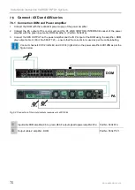
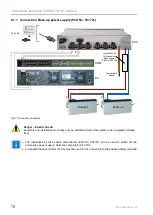
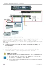
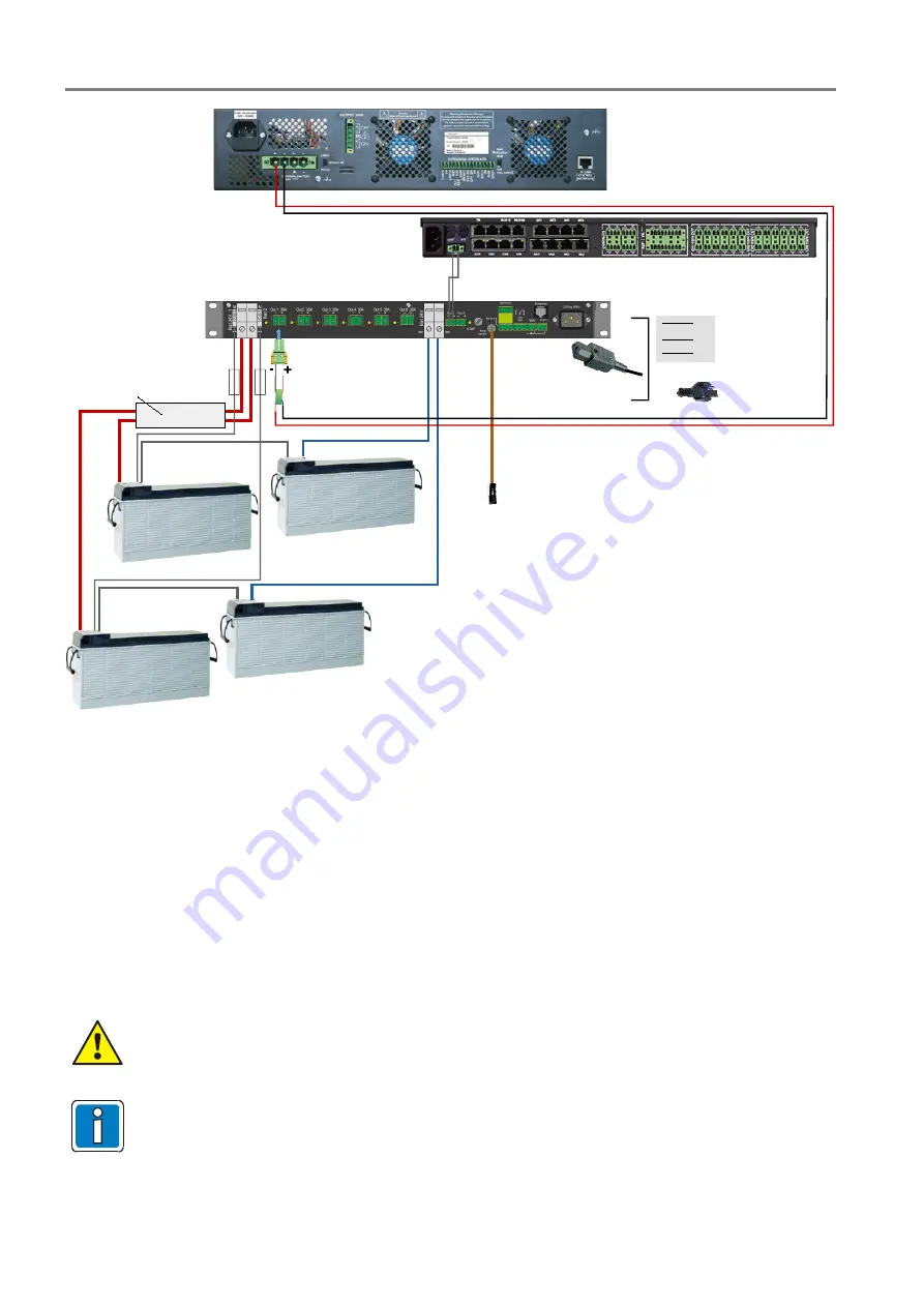
Fig. 78: Sample connection PSU 24V-2 (Part No. 581722 / -24)
Initial commissioning of the VA/PA system using emergency power supply PSU 24V-2 or PSU 24V-4 and the
connected batteries must be completed by a qualified technician, a fire alarm specialist for example.
Installation and commissioning must be completed in accordance with the applicable standards.
Following successful commissioning, there must be no error messages pending in relation to the emergency
power supply.
1.
The battery circuit resistance values (cable cross-sections) for proper operation of the VA/PA system
depend on two factors:
- Battery capacity
- Current consumption during an alarm
2.
The factory-configured resistance parameters can be changed during commissioning. The software
required for this is available online at www.variodyn-d1.com and www.hls-austria.com.
Danger – Electric shock!
Assembly and installation work may only be performed while the system is de-energised (without
power).
•
The installation kit fuse switch disconnector (Part No. 583716) can be used to switch off the
emergency power supply / batteries completely (24 V DC).
•
For more important information and safety information, refer to the documentation provided by
the device manufacturer.

