VBN2, VBN3 CONTROL BALL VALVE/ACTUATOR ASSEMBLIES
Automation and Control Solutions
Honeywell International Inc.
Honeywell Limited-Honeywell Limitée
1985 Douglas Drive North
35 Dynamic Drive
Golden Valley, MN 55422
Toronto, Ontario M1V 4Z9
http://customer.honeywell.com
http://customer.honeywell.ca
® U.S. Registered Trademark
© 2010 Honeywell International Inc.
62-0197—04 E.K. Rev. 04-10
Printed in U.S.A.
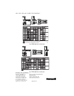
Fig. 8. VB2 dimensions in inches (mm).
Fig. 9. VB3 dimensions in inches (mm).
M31359
INDICATES FULL PORT VALVE: NO FLOW CHARACTERIZING INSERT.
WILL BE SHORTER WITH NON-SPRING-RETURN ACTUATORS.
PIPE SIZE
Cv
DIMENSIONS IN INCHES (mm)
WEIGHT REPLACEMENT
STEM
ASSEMBLY
IN.
1/2
3/4
1
2
3
2-1/2
1-1/4
1-1/2
B,D,E,F,G,H,K
B,D,E,G,H,J,L
J
N,T
N,P,R,T,U
N,P,R,S,U,1
H,J,K,L,N
L,M,R
(DN)
15
20
25
50
80
65
30
40
CODE
DESIGNATORS
2-3/8 (60)
J
2-5/8 (67)
K,M
2-3/4 (70)
2-7/8 (73)
M,N
4-5/16 (109)
M,S
3-5/8 (92)
N,1
4-1/16 (103)
P,R,S,1,2
4-15/16 (125)
2-3/4 (70)
7-1/16 (179)
HLP
3-1/16 (78)
4 (102)
5-3/4 (146)
5-5/16 (135)
3 (76)
3-1/8 (79)
3-7/16 (87)
7-3/16 (183)
7-11/16 (195)
7-9/16 (192)
6-15/16 (176)
A
VBN2A...
VBN2B...
VBN2C...
VBN2F...
VBN2H...
VBN2G...
VBN2D...
VBN2E...
1
2
2
1
1
1
1
1
1
1
1
1
1
1
1
2-3/4 (70)
2-7/8 (73)
3-1/4 (82)
3-1/4 (82)
3-3/4 (95)
4-1/16
(103)
3-1/16 (78)
B
6-7/16 (163)
6-1/2 (165)
6-11/16 (170) 3
(76)
4
(102)
6-5/8 (168)
6-1/2 (165)
7-3/8 (187)
7 (178)
7-1/16 (180)
7-7/16 (189)
6-3/4 (171)
10-11/16 (271)
8-1/8 (206)
1.0 (0.5) 5112-19
5112-22 (SS)
5112-20
5112-23 (SS)
5112-21
5112-24 (SS)
8-5/16 (211)
8-11/16 (221)
8-1/8 (206)
8-5/16 (211)
8-7/8 (225)
9-1/16 (230)
8-7/8 (225)
10-1/2 (267)
8-11/16 (221) 1.4 (0.6)
2.4 (1.1)
2.4 (1.1)
3.2 (1.5)
1.4 (0.6)
C
D
E
F
LB (KG)
A
C
F
E
D
B
M31360
INDICATES FULL PORT VALVE: NO FLOW CHARACTERIZING INSERT.
1
E
D
B
G
A
C
F
PIPE SIZE
Cv
WEIGHT REPLACEMENT
STEM ASSEMBLY
DIMENSIONS IN INCHES (mm)
IN.
1/2
3/4
1
2
2-1/2
1-1/4
1-1/2
B,D,E,F,H,J
C,D,E,F,G
J,L
L,N,P
P,R,S,
H,J,L
H,J,K,M
(DN)
15
20
25
50
65
30
40
CODE DESIGNATORS
3-1/2 (89)
C,D,E,F,G,K
3-5/16 (84)
4-5/16 (110)
K,M,N
3-5/8 (92)
L,P
R,T
5 (127)
3-13/16 (97)
2-13/16 (71)
7-5/16 (186)
9-1/2 (241)
H,K,M
3 (76)
4 (102)
3 (76)
3-13/16 (97)
4-5/16 (110)
7-13/16 (198)
10-13/16 (275)
A
VBN2A...
VBN2B...
VBN2C...
VBN2F...
VBN2G...
VBN2D...
VBN2E...
1
1
1
1
1
4 (102)
4 (102)
4-1/2 (114)
5-13/16 (148)
3-13/16 (97)
B
6-1/2 (165)
6-13/16 (173) 3
(76)
4
(102)
7 (178)
7-13/16 (198)
7-5/16 (186)
7-5/16 (186)
7-13/16 (198)
6-13/16 (173)
2-1/16 (52)
2-3/4 (70)
2-13/16 (71)
2 (51)
2.4 (1.1)
2.4 (1.1)
2.8 (1.3)
2.8 (1.3)
2.6 (1.2)
3.3 (1.5)
3.3 (1.5)
3.8 (1.7)
2.0 (0.9)
5112-19
5112-20
5112-21
3-1/8 (79)
2-7/16 (62)
3-3/16 (81)
3-1/8 (79)
4-1/8 (105)
3-7/8 (98)
2-7/16 (62)
8-13/16 (224)
9-13/16 (249)
9-3/8 (238)
10-13/16 (275)
10-5/16 (262)
11 (279)
12-5/16 (313)
9-13/16 (249)
C
D E
F
G
LB (KG)


