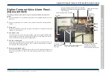
Vigilon
C
ompact
Panel
Installing a replacement MCB in an older Vigilon Compact panel
These instructions cover how to fit a replacement Master Control Board (VCS-MCB-N) into a COMPACT-24-N
(networkable) or COMPACT-24 (non networkable) Vigilon Compact panel.
&
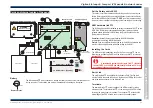
- When a network card is fitted onto the MCB, ensure a spade tab (supplied) is fitted under
the PCB fixing screw at position
u
.
- Also ensure the bottom PCB fixing screw
v
is tightened to give good electrical connection.
How to replace the MCB
There are in existence
four
variants of Vigilon Compact panels in the field. Here are the steps to replace an
MCB
fitted in a Vigilon Compact panel.
Save Configuration to Commissioning tool
¨
If the panel is functioning correctly then before powering down ensure the system configuration is
retrieved using the commissioning tool.
Power down
¨
Completely power down the panel by isolating the mains and battery supply and then remove the
ribbon cable connectors from the
MCB
.
Remove the cards
¨
Remove the
Loop card(s)
and
Network card
# from the
MCB
and then
remove the
MCB
from the panel. (# - where applicable)
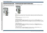
Select the firmware part number and set the rotary switch
¨
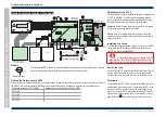
Make a note of the firmware number on the chip in socket IC3 of the
MCB
being replaced. Determine the applicable switch setting
required from the table below and set the rotary switch on the
replacement MCB
.
The firmware in socket
IC3 of
MCB
being
replaced
Applicable setting of switch
SW2 on replacement MCB
2211-148
0
2211-146
1
2211-136
2
2211-127
3
Re-fit the cards
¨
Fit the
replacement MCB
into the panel and reconnect the ribbon
cables, and then fit the previously removed
Network
and
Loop cards
.
¨
An earth lead must be fitted between the spade tabs
u
on
MCB
and
Network card
.
Configuration
¨
Using a chip extractor extract the back up 'Configuration' chip fitted
in socket IC16 (NVM) of the
MCB
being replaced and fit this chip
into the
replacement MCB.
&
Where the Configuration chip is known to be corrupt or
is incompatible then DO NOT fit the chip into the
replacement
MCB
. Instead transmit the saved configuration from the
commissioning tool to the
replacement MCB
. The transmission
must take place after panel power up. After transmitting the
configuration to the panel 'back up' the data to NVM on Card 14.
Power up
¨
Power up the mains and battery supplies to the panel.
Commissioning instructions
36
4188-856_issue 7_07/15_Generic Vigilon (C VA) Comms.
BATT3
PB15
PB6
PB9
P2
CARD 1
IC3
KEYBOARD
IC16
POWER
SUPPLY
P12
MA2 - FS2 250mA
MA1 - FS1 250mA
P1
CARD 2
P16
P13
SW1
RESET
24V
B
A
0V
TX1 RX1 0V
PB8
MA1+ MA1- MA2+ MA2-
0V MIPNC C NO
FIRMWARE BACKUP
PB10
PB7
L1 0V L2 0V
24V
FS3 200mA
TX2 RX2
PB14
L1 0V L2 0V
NC C NO NC C NO NC C NO
PB11
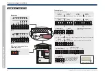
Replacement Master Control Board (MCB)
- networkable
SW2
MODE
OLD Master Control Board (MCB)
- non networkable
P15
P10
P11
P9 P8
P2
CARD 1
IC3
KEYBOARD
PRINTER
IC16
POWER
SUPPLY
P12
MA1 - FS1 250mA
MA2 - FS2 250mA
P1
CARD 2
P16
P13
SW1
CODE
BCKUP
P7
P6
24V
FS3 200mA
P14
BATT1
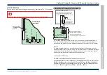
Insulation Disk


