Indications on power up
These are typical power up indications given at the VIGILON, VIGILON Compact and VIGILON
Compact VA panels with no loop circuits connected.
"
At this stage of commissioning the audio loop circuit of VIGILON Compact VA panel
must remain disconnected.
¨
Switch On the mains power to the panel and then connect the battery supply:
•
the panel buzzer sounds
•
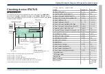
some LEDs on the panel will be momentarily lit and the display reads:
Powering up - please wait
........
•
the dots below the powering up message indicates progress.
•
the
Disablement
light gives a flashing indication and after a short duration change
to a steady indication and the display gives messages similar to:
Time not set
NVM Card Fitted
Audio Card Keypad fitted
-(Compact VA only)
Loop 1; 0V resistance is 28.4R, L is 1
NVM is not write protected
Card found at Card 1 x.xx (aa/bb/cc)
Allocating Loop n
ACC Loop O/S 2
-(Compact VA only)
•
NVM Card - Non Volatile Memory Card found
•
Card 1 - Loop card 1 found
•
Loop 1 has a measured 0V line loop resistance form end to end is 28.4R. The
relative inductance ratio is 1
•
the x.xx is the software version number of the card
•
Audio controller card (ACC) Loop has 2 outstations found this appears on
VIGILON compact VA panel only.
•
the aa/bb/cc signifies the day, month and year of software release.
Allocation: OK at Card X : Allocated zzz
There may be other indications and messages depending on the panel condition.
•
Disablement
indicator is lit.
Initial tests
"
The menus at the control panel are accessible by pressing the Menu On/Off
button. For details of the menu options see Appendix A - Menu Maps .
# - will appear if a PIN is setup.
Display test
¨
To test the display press the
Menu On/Off
button and then select
[Test/Eng]
->
[Disp
Test].
The
Display Test
option will cause all the LEDs and buzzer (including
backlight) to remain On for a short duration.
Setting the Clock
¨
To set up the time and date, press the
Menu On/Off
button and then select
[SetUp]
-> [Usercode]#
->
[Set Clock].
The
Set Clock
option will allow the setting of the time
and date at the panel.
Printer test (if fitted)
¨
To test the printer, press the
Menu On/Off
button and then select
[Control]
->
[Usercode]
# ->
[Printer],
if the printer is On select
[Test]
to carry out a printer test.
Power supply test
¨
Test the panel’s mains and battery supply by carrying out temporary disconnection
and reconnection, to allow event indications to be given on the panel. Ensure
sufficient time is given for the event to be displayed, normally within 2 minutes.
Master alarms circuit tests
¨
Check that indications are given when there is a fault on the master alarm circuit.
Carry out an open circuit test by disconnecting the end of line resistor. Then carry out
a short circuit test by shorting the master alarm circuit terminals.
Commissioning instructions
52
4188-856_issue 7_07/15_Generic Vigilon (C VA) Comms.
Indications
on
power
up


