background image

VISTA-128BP/VISTA-250BP Installation and Setup Guide 

1-4 

Downloading 

• 

Supports upload and download capability. 

• 

Can perform unattended downloading (no one at the downloading computer). 

• 

Provides an Installer Unattended Program Mode. This allows the installer to program the download phone 
number, subscriber number, and primary central station receiver phone number without entering the normal 
program mode. 

• 

Can periodically and automatically perform a scheduled download. 

UL


Unattended and Scheduled Downloading are not UL Listed features. 


• 

Can download access control cardholder information. 

Event Log 

• 

Provides an event log (history log) that can store up to 1000 events. 

• 

Can print the event log on a parallel or serial printer using a VA8201 Alpha Pager Module. 

• 

Can view the event log on an alpha keypad or AUI. 

Additional Features 

• 

Provides up to 60 installer-defined, custom words that can be used for zone descriptors. 

• 

Provides 32 keypad macro commands (each macro is a series of keypad commands of up to 32 keystrokes) using 
the A, B, C, and D keys by partition. 

• 

Provides cross-zone capability, which helps prevent false alarms by preventing a zone from going into alarm 
unless its cross-zone is also faulted within a 5-minute period. 

• 

Contains a built-in User’s Manual, which provides the end user with a brief explanation of the function of a key 
when the user presses any of the function keys on the keypad for 5 seconds.  

• 

Provides trigger outputs, which may interface with Long Range Radio equipment or other devices such as 
keyswitch LEDs, printer, or pager. 

• 

Provides an RS232 input for serial data. This is useful for interfacing the system with Automation software. 
Automation software cannot be used if a serial printer is used on the system. 


At least one 2-line alpha keypad (6139/6160) must be connected to the system for programming (if you are using 
keypad programming), and must remain connected to the system in order to allow the primary user to program 
additional user codes into the system at a later time. 


WWW.DIYALARMFORUM.COM 

WWW.DIYALARMFORUM.COM

Summary of Contents for VISTA-128BP

Page 1: ...V V V VI I I I I I I IS S S S S S S ST T T T T T T TA A A A A A A A 2 2 2 2 2 2 2 25 5 5 5 5 5 5 50 0 0 0 0 0 0 0B B B B B B B BP P P P P P P P V V V V V V V VI I I I I I I IS S S S S S S ST T T T T T T TA A A A A A A A 1 1 1 1 1 1 1 12 2 2 2 2 2 2 28 8 8 8 8 8 8 8S S S S S S S SI I I I I I I IA A A A A A A A Commercial Burglary Commercial Burglary Commercial Burglary Commercial Burglary Partition...

Page 2: ... WWW DIYALARMFORUM COM WWW DIYALARMFORUM COM ...

Page 3: ...ch 3 19 Smoke Detector Reset 3 20 Remote Keypad Sounder 3 20 Installing the VA8200 Panel Link Module 3 21 Long Range Radio Connected to the J7 Triggers 3 22 Long Range Radio Connected to the ECP 3 22 Installing the Alpha Pager Module 3 23 Access Control Using VistaKey 3 25 Access Control Using the PassPoint Access Control System 3 26 Installing a 4100SM 3 27 Installing the 4285 4286 VIP Module 3 2...

Page 4: ...a Master Manager or Operator Code 9 3 Changing a Master Manager or Operator Code 9 4 Adding an RF Key to an Existing User 9 4 Deleting a Master Manager or Operator Code 9 4 Exiting the User Edit Mode 9 4 SECTION 10 Testing the System 10 1 Battery Test 10 1 Dialer Test 10 1 Burglary Walk Test Code 5 TEST 10 1 Armed Burglary System Test 10 1 Testing Wireless Transmitters 10 2 Trouble Conditions 10 3...

Page 5: ...ender Modules 3 13 Figure 3 19 Installing the 5881ENHC with Tamper Protection 3 14 Figure 3 20 5881 RF Receiver cover removed 3 15 Figure 3 21 4204 Relay Module 3 17 Figure 3 22 4204CF Relay Module 3 17 Figure 3 23 Wiring the FSA Module 3 18 Figure 3 24 Ground Start Module Connections 3 19 Figure 3 25 Remote Keyswitch Wiring 3 20 Figure 3 26 Remote Keypad Sounder Wiring 3 20 Figure 3 27 Panel Link...

Page 6: ...ates a critical note that could seriously affect the operation of the system or could cause damage to the system Please read each warning carefully This symbol also denotes warnings about physical harm to the user ZONE PROG 1 YES 0 NO 0 Many system options are programmed in an interactive mode by responding to alpha keypad display prompts These prompts are shown in a single line box 00 Additional ...

Page 7: ...AUI Panel Link Module VA8200 Voice Keypad 6160V An ECP Long Range Radio that can send Contact ID messages An access control system by using either the ADEMCO PassPoint system via the VISTA Gateway Module or a VistaKey module via the polling loop UL The access control function is not Listed for use with the VISTA 128BP VISTA 250BP Control Panel in a UL installation The system supports either the Vi...

Page 8: ... and individual relays up to 32 as well as system zones RF receivers and keypad panics Provides 96 outputs using 4204 and 4204CF Relay Modules Fire System Annunciators FSA 8 FSA 24 V Plex Relay Modules and X 10 devices can activate outputs in response to system events alarm condition at a specific time of day at random times and manually using the 70 Relay Command Mode Supports the ADEMCO 4285 428...

Page 9: ... functions such as arming disarming and activation of outputs e g lights Provides access schedules for limiting system access to users by time Provides an End User Output Programming Mode allowing the user to control outputs Access Control Supports up to 15 VistaKey modules 15 access points VISTA 128BP supports 8 modules which are used for access control It is a single door access control module S...

Page 10: ...2 keypad macro commands each macro is a series of keypad commands of up to 32 keystrokes using the A B C and D keys by partition Provides cross zone capability which helps prevent false alarms by preventing a zone from going into alarm unless its cross zone is also faulted within a 5 minute period Contains a built in User s Manual which provides the end user with a brief explanation of the functio...

Page 11: ...e GOTO is enabled for each partition he she wants to log on to from another A partition can be selected as a common lobby partition and other partitions can affect this partition by causing arming disarming of this partition to be automated see Common Lobby Logic later in this section Setting Up a Partitioned System The basic steps to setting up a partitioned system are described below If you need...

Page 12: ...tion arms Can be armed if other partitions disarmed 0 0 NO NO YES 1 0 YES NO NO 1 1 YES YES NO 0 1 ENTRY NOT ALLOWED Example Here is an example of how the lobby would react in a typical setup OFFICE 1 OFFICE 2 MAIN ENTRANCE COMMON LOBBY V128BP 001 V0 User 1 has access to Office 1 and the Common Lobby User 2 has access to Office 2 and the Common Lobby Office 1 is set up to affect the Common Lobby b...

Page 13: ...eration Although this system has eight actual partitions it provides an extra partition strictly for the purpose of assigning keypads as Master keypads for the system Assigning any keypad to Partition 9 in Device Programming in the 93 Menu Mode makes that keypad a Master keypad A Master keypad reflects the status of the entire system Partitions 1 8 on its display at one time This is useful because...

Page 14: ... when added to the system An alpha keypad must be used for panel linking The system may take up to 7 seconds to respond to a command when in a panel linking mode NOTE A user cannot access partitions or panels that they have not been assigned to Panel Link Module Supervision The Panel Link Module can be supervised for its connection to the control panel The module s supervisory zone is zone 8xx whe...

Page 15: ...78 are the partition numbers and xxxxxxxx is the status of each partition of that panel Status indications include A Armed Away S Armed Stay M Armed Maximum I Armed Instant R Ready N Not Ready B Bypassed Ready Alarm T Trouble F Fire Alarm P AC Power Failure L Low System Battery C Comm Fail NOTES See table later in this section for priority of displays A under a partition number indicates the user ...

Page 16: ...d displays the status of the original partition of the original panel for the keypad Also this mode will end in approximately 120 seconds if no keys are pressed NOTES When performing any of the arming commands if there are faults in any of the partitions of a panel the system will not arm that panel but will arm all the other partitions of the other panels When performing either a STAY or INSTANT ...

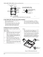
Page 17: ...he latch will make contact with the latch bracket when the door is closed 3 When correctly positioned push the lock until it is held securely by its snap tabs Use an ADEMCO No K4445 Lock supplied CABINET DOOR BOTTOM LOCKED UNLOCKED cab_lock_snap 001 V0 ADEMCO ADEMCO PUSH SNAP TAB SNAP TAB PUSH ON LOCK UNTIL IT IS SEATED SECURELY STEP 2 STEP 1 CHECK POSITION Figure 3 1 Installing the Lock Grade A M...

Page 18: ...must be wired to a hardwire zone Installing the Control s Circuit Board To install the circuit board in the cabinet perform the following steps Step Action 1 Hang the three mounting clips on the raised cabinet tabs Refer to Figure 3 3 Detail B Make sure the clip orientation is exactly as shown in the diagram to avoid damage This will also avoid problems with insertion and removal of the PC board 2...

Page 19: ...o Control Panel Addressing the Keypads The keypads will not operate until they are physically addressed and enabled in the system s Device Programming in the 93 Menu Mode Set each keypad for an individual address 00 30 according to the keypad s instructions Set an alpha keypad for address 00 and other keypads for higher addresses 00 and 01 are enabled in the system s default program Any keypads se...

Page 20: ...xcess of 750mA Non UL Installations For non UL installations the total current drawn from this output can be up to 1 7 amps A battery must be installed as the battery supplies current in excess of 750mA Up to two 719 sirens can be used wired in parallel UL This control complies with National Fire Protection Association NFPA requirements for temporal pulse sounding of fire notification appliances A...

Page 21: ...Cut the blue jumper on the upper left hand corner of the panel s PC board 4 Program Zone 970 with no response type 00 Disabling the Supervision of the Alarm Output To install the alarm output and disable the supervision feature perform the following steps Step Action 1 Wire the devices to terminals 4 and 5 observing polarity if necessary 2 Cut the blue jumper on the upper left hand corner of the p...

Page 22: ...gh side of the loop The 2K EOL resistor must be connected in series with the devices following the last device Connect N O devices in parallel across the loop The 2K EOL resistor must be connected across the loop wires at the last device N C N C N O 2k EOLR 2k EOLR N C N C 2k EOLR 2k EOLR N C N C N C 2k EOLR SMOKE Zone resistance Excluding EOLR ZONE 1 8 100 OHMS MAXIMUM ALL OTHER ZONES 300 OHMS MA...

Page 23: ...sistor must be connected across the loop wires at the last detector 2k EOLR ZONE 1 SMOKE 2 WIRE SMOKE DETECTOR 10 11 Figure 3 10 2 Wire Smoke Detector on Zone 1 Using 4 Wire Smoke Detectors on Zones 1 8 You may use as many 4 wire smoke detectors as can be powered from the panel s Auxiliary Power output without exceeding the output s rating 750mA NFPA limits the number of 4 wire smoke detectors to ...

Page 24: ...3PRM may be used with the System Sensor 2112 24AT and similar models with the required operating features previously stated The 333PRM reverses polarity to smoke detectors with Integral Temp 3 Sounders Typically in alarm each draws 49 60mA of current The control panel supplies only enough current for one smoke detector In order to attach more than one an external power supply and an external relay...

Page 25: ...L 2 3 4 1 12 7 6 4 Figure 3 12b Wiring a 333PRM using a 4204 EOL POWER SUPERVISION RELAY MODULE A77 761B 4 WIRE SMOKE DETECTORS 2000 OHM EOLR TO FIRE ZONE TERMINALS HEAT DETECTOR SHOWN POWERED RELAY OPENS WHEN POWER IS LOST 333PRM 003 V0 POWER SUPPLY 333 PRM 7 6 5 4 3 2 1 8 JUMPER P1 USE A 12VDC BATTERY BACKED UL LISTED POWER SUPPLY JUMPER P1 ON 333 MODULE MUST BE IN B POSITION FOUR WIRE DETECTOR ...

Page 26: ...ct detectors across zone 8 terminals 21 and 22 See Figure 3 13 3 Connect the EOL resistor at the last detector in the loop across the zone s terminals You must connect the EOL resistor across the loop wires at the last detector Tamper Supervision for the Hardwired Zones The system can be programmed to monitor for either an open condition or a short condition of a tamper switch on zones 1 8 End of ...

Page 27: ...eparate enclosure that has a tamper supervised cover The 4190WH right loop must not be used and the left loop must be EOLR supervised The 4278 right loop cannot be used The 4194 is not UL Listed The 4297 must be powered from the control panel s Auxiliary Power Output or from a UL Listed supplementary power supply The 7500 and 9500 detectors are not UL Listed For new polling loop installations alwa...

Page 28: ...oftware all the devices may be connected before powering up to program POLLING LOOP RATING 128mA MAXIMUM 4192SD SMOKE 4190 RPM 4278 PIR 23 21 22 POLLING LOOP 25 24 TO RIGHT LOOP poll_loop 001 V0 Figure 3 16 Polling Loop Connections to the VISTA 128BP VISTA 250BP Polling Loop Supervision A short on the polling loop is indicated by a trouble on zone 997 and reports as a trouble condition only If ann...

Page 29: ...GTH OF ALL WIRE RUNS ON THE INPUT LOOP AND EXTENSION LOOP 2 COMBINED CANNOT EXCEED 6400 FT 3200 FT IF USING UNSHIELDED WIRE IN CONDUIT OR SHIELDED WIRE 4297 RPM INPUT POLLING LOOP DO NOT CONNECT 4297 MODULES IN SERIES i e DO NOT CONNECT ONE MODULE S EXTENSION LOOP TO ANOTHER MODULE S INPUT LOOP polling_loop 004 V1 EXTENSION POLLING LOOP 2 Figure 3 18 Polling Loop Connections Using Multiple Extende...

Page 30: ...om the control panel or any keypads to avoid interference from the microprocessors in these units If dual receivers are used a They must be at least 10 feet from each other as well as from the control panel and remote keypads b Each receiver must be set to a different device address The receiver set to the lower address is considered the 1st RF receiver for supervisory purposes c The House IDs mus...

Page 31: ... must not be installed within the control cabinet It must be between one and two feet from the receiver s antennas 2 Set the module for the appropriate address For Address Setting 28 cut the red jumper for Address 29 cut the white jumper for Address 30 cut both jumpers Make sure the address setting is not being used by another device keypad relay module etc 3 Connect the module s wire harness to t...

Page 32: ...act ID as a Fire Trouble 373 not Loss of Supervision 381 to the central station Transmitter Battery Life Batteries in the wireless transmitters may last from 4 to 7 years depending on the environment usage and the specific wireless device being used Factors such as humidity high or low temperatures as well as large swings in temperature may all reduce the actual battery life in a given installatio...

Page 33: ...OL GROUND DATA OUT TO CONTROL 12V YEL BLK GRN RED Figure 3 21 4204 Relay Module SWITCH 4 2 0 4 C F A D D R E S S S E T T I N G S POSITION means OFF 0 1 2 3 4 5 6 7 8 9 10 11 12 13 14 15 2 ON ON ON ON ON ON ON ON 3 ON ON ON ON ON ON ON ON 4 ON ON ON ON ON ON ON ON 5 ON ON ON ON ON ON ON ON ON 1 2 3 4 5 OFF ON 13 14 15 16 NC NC DIP SWITCH FOR SETTING DEVICE ADDRESS AND ENABLING DISABLING TAMPER COVE...

Page 34: ...ransformer X 10 devices respond to on and off commands sent from the panel through the 1361X10 transformer To connect the 1361X10 transformer see Connecting the Transformer later in this section Installing the Ground Start Module UL The Ground Start Module is not intended for use in UL Listed applications Output 1 may be used to trigger an optional 675 Ground Start Module for installations having ...

Page 35: ...uent short disarms the partition The keyswitch LEDs indicate the partition s status see table below A momentary short across Zone 7 silences alarm bell and keypad sounds and disarms the system if it was armed A subsequent short across Zone 7 clears the alarm memory indication and resets 2 wire smoke and glassbreak detectors if used LED Indications Green Red Indication On Off Disarmed Ready Off Off...

Page 36: ...e Keypad Sounder This feature is available in the VISTA 128BP only An optional Amseco PAL 328N Piezo Sounder can be used to duplicate the sounds produced by the keypad s built in sounder The panel will remote all sounds e g alarm trouble chime entry exit etc produced by the keypad s built in sounder except for the short beeps associated with keypad key depression One application of this feature mi...

Page 37: ...eral buildings are to be connected the RS 485 bus should form a continuous path from one building to the next Avoid wiring units in a star configuration where multiple branches are formed Star configurations create loading and capacitance problems that are complex and become difficult to troubleshoot Mounting and Wiring the Panel Link Module The PLM will not operate until the device is enabled in ...

Page 38: ...elay expires Report is removed from queue and no message is sent to LRR Primary Phone No 0 Not acknowledged before delay expires Report is sent to both the Primary Phone No and LRR Acknowledged before delay expires Report is removed from queue and no message is sent to Primary Phone No Long Range Radio 1 Not acknowledged before delay expires Report is sent to both the Primary Phone No and LRR Addi...

Page 39: ... it uses Event Code 341 expansion device tamper Installing the Alpha Pager Module The VA8201 Alpha Pager Module APM is used for the transmission of alphanumeric messages to a user subscribed Paging Service The APM can be programmed to send the information to up to 8 different paging services In addition the module can direct the event log reports to a parallel or serial printer and can interface t...

Page 40: ... Pager Module on the cabinet door or attempt to attach it to the PC board To mount the Alpha Pager Module perform the following steps Step Action 1 If you are mounting the Alpha Pager Module inside the control cabinet attach it to the cabinet s interior surface with 2 faced adhesive tape 2 If you are mounting the Alpha Pager Module outside the cabinet use the bracket interface Ademco Part Number K...

Page 41: ...h VistaKey communicates with the VISTA 128BP VISTA 250BP via the V Plex polling loop In the event local power to the VistaKey is lost the VistaKey module provides backup monitoring of the access point door via a built in V Plex device that is powered solely from the polling loop It is programmed as a new type of V Plex device as part of the control s V Plex Device Programming A serial number label...

Page 42: ...TERMINAL 7 TRIGGER RATING IS 15mA AT 12VDC 5V GND TRIGGER SEE NOTE 3 12V RED ZONE C General ZONE A DSM ZONE B RTE POLLING LOOP 14V MAX 12V 85 160mA Nominal POLLING LOOP GND GND GND N O DOOR STRIKE POWER N C MAG COIL POWER 2 3 4 5 6 7 8 1112 2 3 4 5 6 7 8 9 10 1 RELAY CONTACT RATINGS 3A 28VDC MAX RESISTIVE LOAD TB 1 TB 3 1 READER INTERFACE CABLE GND BLACK RDR LED ORANGE TO ALARM SYSTEM CONTROL PANE...

Page 43: ...ol 4 Connect terminals 8 and 7 of the 4100SM to terminals 6 and 7 aux power and respectively of the control 5 Connect the UL EDP Listed serial printer to the 4100SM Interface Module The 4100SM Module is supplied with a 10 foot RS232 cable A longer cable can be used if the VISTA 128BP VISTA 250BP is separated from the serial printer by more than 10 feet but the total cable length should be less tha...

Page 44: ... the same words that would normally be displayed on an alpha keypad under the same system conditions Refer to the words in bold on the Alpha Vocabulary list found in the 93 Menu Mode in the Programming Guide Can be supervised for connection to control panel annunciated and reported as Zone 804 The 4285 4286 is wired between the control panel and the premises handset s see Figure 3 35 It listens fo...

Page 45: ...s phones will not operate YELLOW NO CONNECTION RED BLACK GREEN TO CONTROL PANEL KEYPAD CONNECTIONS KEYED HEADER 1 2 3 4 5 6 7 NO CONNECTION 4286 VIP MODULE ANSWERING MACHINE PREMISES ANSWERING MACHINE AND PHONES TIP RING RJ31X JACK TIP RING INCOMING TELCO LINE CALLER ID UNIT IMPORTANT NOTE FOR EXISTING INSTALLATIONS EXISTING WIRES CONNECTED TO THE HANDSET TERMINALS ON CONTROL MUST BE MOVED FROM TH...

Page 46: ...r wiring connections For a detailed explanation of the wiring connections and the functions of the DC power jack and terminal block positions refer to the installation instructions that accompany the UVS If the phone plug is disconnected from the control the premise s phones will not operate NOTES When the AAV indicates that the audio alarm verification session is completed all keypad sounds are r...

Page 47: ...OME CONTROL PANELS USE BUILT IN TRIGGER AND SOME USE 4204 RELAY MODULE REFER TO AAV SECTION OF CONTROL PANEL INSTALLATION AND SETUP GUIDE FOR CONNECTION NOTE 4 EITHER MUSIC SOURCE OR 4286 VIP MODULE CAN BE USED BUT NOT AT THE SAME TIME NOTE 5 DO NOT CONNECT IF 4286 VIP MODULE IS USED 1 2 3 4 5 6 7 8 9 10 11 12 13 14 15 16 17 18 19 20 21 22 23 24 25 26 27 28 29 30 31 32 33 34 SELECT APPROPRIATE INP...

Page 48: ...Ohm speaker to TeleSmart s speaker terminals Figure 3 38 5 Disconnect those keypads intended to be used with TeleSmart from the control s terminals if previously connected Step Action Connect keypad wiring as shown in Figure 3 39 see the chart below for the maximum wire run length for wire gauge you are using NOTE Run audio cable in separate 2 conductor twisted pair cable 22AWG recommended This ca...

Page 49: ...REMISES PHONES GREEN RED GREY BROWN RING TIP FROM CONTROL HOME PHONES phon_conn V0 Figure 3 37 TeleSmart Phone Connections NOTE If the system hangs up the phone line when calling in from a remote location check the phone connection terminals Term 17 18 from control Term 15 16 to house phones 8 ohm Speaker 1 2 3 4 5 6 7 8 9 10 11 12 13 14 15 16 17 18 AUX SPEAKER Figure 3 38 TeleSmart Speaker Connec...

Page 50: ...AY 5 TEST 8 CODE 0 3 STAY 6BYPASS 9CHIME ARMED READY MESSAGE Figure 3 39 Keypad Connections REAL TIME CLOCK RTC 1 2 3 4 5 6 7 8 9 10 11 12 13 14 15 16 17 18 EARTH GROUND TYPICAL CONTROL S AC TERMINALS Figure 3 40 RTC and Ground Connections 1 2 3 4 5 6 7 8 9 10 11 12 13 14 15 16 17 18 YEL DATA OUT RED 12VDC GRN DATA IN BLACK GND TO CONTROL S KEYPAD TERMINALS Figure 3 41 TeleSmart to Control Connect...

Page 51: ...bserve the auxiliary power current rating will result in a battery that does not charge properly or possibly a tripped circuit breaker To connect the transformer to the control perform the following steps Step Action 1 Connect all installed devices to the control 2 Wire the 1361 Transformer 1361CN in Canada to the panel before connecting the battery as shown in Figure 3 42 or wire the 1361X10 Tran...

Page 52: ...uires the earth ground connection for its lightning transient protection devices Determining the Control s Power Supply Load Use the tables that follow to calculate the total current for the Auxiliary Power the Alarm Output and the Polling Loop In each table multiply each device s standby and or alarm current by the number of units used 1 In Table 1 enter devices used on the polling loop Calculate...

Page 53: ...ed must be limited to 270mA when 14AH batteries are used and to 390mA when 17 2AH batteries are used DO NOT use Gates batteries sealed lead acid type These batteries require a different charging voltage than is supplied by the panel UL Household Fire or Combination Household Fire Burglary installations require the use of a backup battery that is capable of providing 24 hours of standby time follow...

Page 54: ...et only 14AH Yuasa NP7 12 Connect two in parallel 17 2AH Yuasa NPG18 12 Fits in large mercantile cabinet only 7 Connect the battery referring to Figure 3 42 The standby battery is automatically tested for 10 minutes every 4 hours beginning 4 hours after exiting Programming mode In addition entry into the Test mode initiates a battery test The VISTA 128BP VISTA 250BP also runs a 5 second battery te...

Page 55: ...ter Programming mode b Press 9 9 Exiting by this method permits the installer code to be being used to re enter Programming mode Data Field Programming Mode In the Data Field Program Mode you may access any field simply by entering either or the field number To write or change information in a field press the field number 03 To read the information in a field press the field number 03 When the ent...

Page 56: ...he keypad displays the last entry and waits To proceed enter the next data field you wish to program Programming Partition Specific Data Fields To program partition specific data fields once in Program Mode do the following Step Action 1 Enter Program Mode Installer Code 8 0 0 0 2 Press 91 which will prompt you for the partition number desired 3 Enter a partition specific field number e g 09 to be...

Page 57: ...tput relay modules 4204 4204CF FSA FSA 8 FSA 24 4285 4286 VIP Module Panel Link Module VA8201 ECP long range radio 7845C and VISTA Gateway Module Device Address Device Type Keypad Options including Partition assignment RF House ID LRR Options including Programming radio OUTPUT PGM 1 YES 0 NO 0 For defining output device functions RLY VOICE DESCR 1 YES 0 NO 0 For entering voice descriptors for rela...

Page 58: ...ss zone Programming of the zone response type is not applicable This zone requires only the report code programming Zone 004 is also defaulted with Auto STAY enabled Zone Index The zones are designated as follows ZONE RANGE ZONE FUNCTION ACTUAL ZONE 001 250 Protection zones As indicated 601 632 Relay Supervisory Zones 6 2 digit Relay Number e g Relay Number 03 is zone 603 800 830 ECP Device Superv...

Page 59: ...6 00 175 10 00 29 14 00 78 03 00 127 07 00 176 11 00 30 15 00 79 04 00 128 08 00 177 12 00 31 01 00 80 05 00 129 09 00 178 13 00 32 02 00 81 06 00 130 10 00 179 14 00 33 03 00 82 07 00 131 11 00 180 15 00 34 04 00 83 08 00 132 12 00 181 01 00 35 05 00 84 09 00 133 13 00 182 02 00 36 06 00 85 10 00 134 14 00 183 03 00 37 07 00 86 11 00 135 15 00 184 04 00 38 08 00 87 12 00 136 01 00 185 05 00 39 09...

Page 60: ...zone type to all exterior door and window zones Type 04 Interior Follower Provides a delayed alarm using the programmed entry delay time if an entry exit zone is faulted first Otherwise it produces an instant alarm It is active when the system is armed in the AWAY or MAXIMUM mode but the MAXIMUM mode eliminates the entry delay If the Interior Follower zone is programmed for one of the STAY modes d...

Page 61: ...between the MLB and the VISTA Gateway Module VGM fails a trouble condition is annunciated for the zone Also if the communication fails all access control system ACS input zones also display a CHECK Type 29 Momentary Exit Used to cause an access point programmed for entry to revert to an exit point for 15 seconds After the 15 seconds it automatically reverts back to an entry point This zone type sh...

Page 62: ...taKey General Purpose GP This input type operates in the same manner as other VISTA 128BP VISTA 250BP alarm panel zones and is provided so that a zone in the proximity of the VistaKey can be wired without having to run additional wiring from the control panel Programming for Panel Linking Step Action 1 Program the Panel Link Module PLM into the system in Device Programming in the 93 Menu Mode with...

Page 63: ...to the control s event log This is enabled in the PassPoint ACS See the PassPoint ACS documentation for a detailed explanation Programming the VISTA Gateway Module See the PassPoint ACS instructions to program the VISTA Gateway Module Using ACS Zone Inputs If the PassPoint ACS has uncommitted zones these may be used by the VISTA 128BP VISTA 250BP as hardwired zones To program for ACS zone inputs p...

Page 64: ...Output Programming in the 93 Menu Mode 2 Program all the information for the relay 3 Select the output type ECP 1 4204 or 2 X 10 See Output Programming in the Programming Guide for a detailed explanation Using the VISTA 128BP VISTA 250BP for Stand Alone Access Control The VISTA 128BP VISTA 250BP can be used for access control without interfacing to PassPoint ACS or VistaKey A user can trigger an a...

Page 65: ...LE and DATA ENTRIES EXPLANATION 00 Installer Code Enter 4 digits 0 9 The Installer Code is a 4 digit code reserved for installation company use This is the only code that can be used to enter the Program Mode from the keypad This code cannot be used to disarm the system if it isn t used to arm the system This code cannot be used to re enter Program Mode if Program Mode is exited by the 98 command ...

Page 66: ...ay must be set for a minimum 45 seconds 13 Alarm Sounder Duration partition specific Enter 01 15 multiplied by 2 minutes 00 no timeout Defines the length of time the Bell Output and the keypad s sounder will sound for all audible alarms Must be minimum 16 minutes for UL Commercial Burglary installations SIA Guidelines Must be minimum 6 minutes Burglary or RS232 Input 0 burglary 1 RS232 input If en...

Page 67: ...ensors with tamper switches or 5800 Series transmitters Must be 0 for UL installations 25 Burglary Trigger for Response Type 8 0 disable 1 enable If enabled allows triggering of Output 3 pin 7 of the J7 header to include zone response type 8 24 hr auxiliary 26 Intelligent Test Report 0 disable 1 enable If enabled no test report is sent if any other type of report was sent since the last test repor...

Page 68: ... up to 17 digits The secondary phone number is used if communication on the primary number is unsuccessful or if split dual reporting is desired Do not fill unused spaces NOTE If this field is programmed a secondary subscriber account number field 90 must also be programmed 35 Download Phone Number Enter 0 9 11 for 12 for 13 for a 2 second pause Enter the downloading phone number up to 17 digits D...

Page 69: ... will be used NOTES Do not enter 00 if a 4285 4286 is installed In the Answering Machine Mode the caller should let the phone ring once then hang up and call again within 30 seconds The system upon hearing one ring followed by nothing does not answer the first call but readies itself to pick up on the first ring of the next incoming call that is received within 30 seconds i e the downloader callin...

Page 70: ...0 15 times 15 seconds Select the time the panel should wait for acknowledgment from the first reporting destination before it attempts to send a message to the second destination first and second destinations are determined in field 57 NOTE If the acknowledgment is received before the delay time expires no message is sent to the second destination 57 Dynamic Signaling Priority 0 Primary Dialer 1 L...

Page 71: ... Number partition specific Enter 00 09 B F 11 15 Enter a 3 or 4 digit depending on report format primary subscriber account number Each number requires a 2 digit entry so as to allow entry of hexadecimal digits B F If a 3 digit account number is to be used enter data only in the first 3 locations and enter in the fourth location NOTE This field must be programmed if a secondary phone number is use...

Page 72: ...d UL Exit Error Logic is not suitable for use in a UL installation 1 20 Exit Delay Reset 0 disable 1 enable If enabled when the panel is armed the normal exit delay begins After the user exits closes the door and then re enters the premises the exit delay time is reset to the programmed value NOTES Exit Delay Reset is designed to allow an operator to re enter the premises to retrieve a forgotten i...

Page 73: ...ed within a five minute period to cause an alarm Must be 000 000 for UL installations 1 23 Cross Zoning Pair Two Enter 001 250 Enter 000 000 to disable Select the second pair of cross zones which must both be faulted within a five minute period to cause an alarm Must be 000 000 for UL installations 1 24 Cross Zoning Pair Three Enter 001 250 Enter 000 000 to disable Select the third pair of cross z...

Page 74: ...y all others to secondary 2 Open Close and Test reports to secondary all other reports to primary Select the type of split reporting for system communication NOTE See 51 for split dual reporting combinations 1 35 Access Control Dialer Enables 0 disable 1 enable There are six entries for this field as follows Trace Trouble Not Used Bypass System Alarm If Trace is enabled access grant denial events ...

Page 75: ...isable 1 enable If enabled no trouble soundings occur on the keypad for transmitter check in failures Must be 0 for UL 1 52 Send Cancel If Alarm Off partition specific 0 disable 1 enable If enabled Cancel reports are sent when the system is disarmed after an alarm regardless of how much time has gone by If disabled Cancel reports are sent within Bell Timeout period only NOTE This option must be en...

Page 76: ...inutes Enter 000 127 times 2 minutes 000 254 This is used for 80 Menu Mode Time Driven event relay command numbers 04 09 and Output Programming in the 93 Menu Mode Programming output command 56 1 75 Relay Timeout YYY Seconds Enter 000 127 seconds This is used for 80 Menu Mode Time Driven event relay command numbers 05 10 and Output Programming in the 93 Menu Mode Programming command 57 1 76 Access...

Page 77: ... order to prevent false alarms if the user arms the system then re enters the premises for example to retrieve a forgotten item Openings and closings are still recorded in the event log This field must be set to 1 if No Opening and No Closing reports are to be sent 2 10 Allow Disarming Only During Arm Disarm Windows partition specific 0 disable 1 enable If enabled disarming of the system is allowe...

Page 78: ...able if the alphanumeric pager interface is installed 2 31 Delay Paging 0 disable 1 enable This field has eight locations one for each pager If enabled the system waits the delay time specified in field 2 32 before transmitting the message after the dialer completes sending the message 2 32 Time to Delay Pager After Dialer 000 024 times 10 seconds 010 240 This delay should be set to allow enough t...

Page 79: ...y occurs after the pager ID is sent and before the event information is sent NOTE Program only if using numeric format 2 45 Pager 2 Partition Enable 0 disable 1 enable This field has eight entries one for each partition If enabled the system sends messages to Pager 2 for the partition s 2 46 Pager 2 Trigger Event Enables 0 disable 1 enable This field has five entries as follows Alarm Trouble Bypas...

Page 80: ... This delay occurs after the pager ID is sent and before the event information is sent NOTE Program only if using numeric format 2 59 Pager 4 Partition Enable 0 disable 1 enable This field has eight entries one for each partition If enabled the system sends messages to Pager 4 for the partition s 2 60 Pager 4 Trigger Event Enables 0 disable 1 enable This field has five entries as follows Alarm Tro...

Page 81: ...ogram only if using numeric format 2 73 Pager 6 Partition Enable 0 disable 1 enable This field has eight entries one for each partition If enabled the system sends messages to Pager 6 for the partition s 2 74 Pager 6 Trigger Event Enables 0 disable 1 enable This field has five entries as follows Alarm Trouble Bypass Open Close System If enabled the system sends a signal to the pager 2 75 Pager 7 P...

Page 82: ...the pager format for Pager 8 2 85 Pager 8 Delay 1 000 060 seconds This delay occurs after the phone number is dialed and before the pager ID is sent giving the pager system time to answer the phone call NOTE Program only if using numeric format 2 86 Pager 8 Delay 2 000 060 seconds This delay occurs after the pager ID is sent and before the event information is sent NOTE Program only if using numer...

Page 83: ... set from 1 to 15 minutes prior to the arming in partition specific program field 2 06 During this period the keypad beeps every 15 seconds and displays AUTO ARM ALERT During the last 60 seconds the keypads beep every 5 seconds The panel arms at the conclusion of the Auto Arm Warning period Extend Closing Window A user can manually delay the arm closing time window by 1 or 2 hours This is done by ...

Page 84: ...r the end of the time window The system can perform the same actions on a daily basis or can perform an action only once e g turn on the porch light this Wednesday at 8 00 PM The system also provides up to 20 programmable timers available to the end user for the purpose of activating output devices at preset times and days Time Window Definitions Scheduled events are based on time windows periods ...

Page 85: ...de the assigned time window The system keeps a record of all openings closings in its event log If a disarming occurs during a closing window for example a person who arms the system forgets something and has to re enter the Opening report although outside of the opening window will not be sent as long as that disarming occurs within the closing window This option is programmed in partition specif...

Page 86: ...Installation and Setup Guide In order to use 80 Scheduling Menu Mode use the worksheets to do the following 1 Define time windows up to 20 2 Define the daily open close schedules one schedule per day per partition 3 Define the holidays to be used by the system up to 16 4 Define limitation of access times up to 8 schedules 5 Define the Time Driven events up to 20 NOTE Temporary schedules are progra...

Page 87: ...me Window Number Start Time HH MM Stop Time HH MM 1 2 3 20 A time window must have a start and a stop time Time Windows Programming Enter Scheduling Mode by entering Installer Code 80 The keypad displays the Time Window Programming prompt PROMPT EXPLANATION Time Window 1 YES 0 NO 0 Enter 1 at this main menu prompt to program time windows Time Window 01 20 00 Quit 01 Enter the 2 digit time window n...

Page 88: ... for a particular day As the number is keyed in the actual time that has been stored for that window number is displayed as a programming aid Press to accept the entry Mon P1 CL WIND 00 00 00 00 00 Enter the time window number for the displayed day s closing schedule As the number is keyed in the actual time that has been stored for the window number is displayed Press the key to accept the entry ...

Page 89: ...gned The Holiday Number prompt is displayed again Repeat the procedure for each holiday to be programmed Quit 1 YES 0 NO 0 Enter 0 at the Quit prompt to return to the main menu choices and continue programming Enter 1 to quit Scheduling Menu Mode Time Driven Events These schedules are used to activate outputs bypass zones etc based on time There are 20 of these schedules that may be programmed for...

Page 90: ... Partition s 25 Arm INSTANT Partition s 26 Arm MAXIMUM Partition s The auto arm warning field 2 06 applies when using Time Driven events to auto arm Temporary schedules do not override an auto arming or auto disarming programmed in Time Driven events The auto arming window cannot be extended using the Installer Code 82 Mode Bypass Commands Action Code Action Action Specifier 30 Auto bypass Zone li...

Page 91: ...ices programmed for randomization assigned to the partition the sequence is entered in Enter the sequence again to turn off the random schedule User Code 42 This is the same as the method above except the randomization occurs only on devices with activation times within 6 PM and 5 AM Enter the same sequence again to turn off the random schedule UL You must not program Random Scheduling of Time Dri...

Page 92: ...ppears Enter the zone list number that contains the zones to be bypassed or unbypassed Press to accept entry The Time Window prompt appears 01 ZONE LIST ENTER 01 15 01 42 Enable Access Window for Access group s Action 42 If you selected action 42 the prompt at the right appears Enter the group number to which the time window will apply Press to accept entry The Time Window prompt appears GROUP 123...

Page 93: ... of the window 4 Trigger at both the start and the end of the window Example coffee break buzzer 5 Random trigger up to 30 minutes after the start of the window 6 Random trigger up to 30 minutes after the end of the window 7 Take effect only for the duration of the window but random start and end the window up to 30 minutes Press to accept entry Days MTWTFSSH Hit 0 8 x x The system then asks for w...

Page 94: ...hat has been stored for the window is displayed Press to continue TUE A1 Window 1 00 00 00 00 00 Repeat the procedure for the other days of the week When the last day of the week has been programmed the windows for holidays may be entered Hol A1 Window 1 00 00 00 00 00 Enter the first time window number for holidays for this access schedule As the number is keyed in the actual time that has been s...

Page 95: ... tens of hours digit of the start time of the arm window Enter the hour Press to move to the minutes field The minutes are entered in the same manner Press to move to the AM PM position Pressing any key in the 0 9 range toggles the AM PM indication Repeat the procedure for the stop time entry After the windows for that day have been completed the system prompts for disarm and arm time windows for ...

Page 96: ...Mode PROMPT EXPLANATION 06 ON TIME 07 00 PM The cursor is positioned on the tens of hours digit of the ON time Enter the desired hour Press to move to the minutes field The minutes are entered in the same manner The AM PM indication is toggled by hitting any key from 0 9 while the cursor is under the AM PM position Press to continue 06 OFF TIME 11 45 PM The cursor positioned on the tens of hours d...

Page 97: ...ice must be matched between the control and computer 2 Hang up and callback The control panel hangs up and calls the computer back at the pre programmed number only if the security codes match 3 Data encryption All data that is exchanged between the computer and control is encrypted to reduce the possibility of anyone tapping the line and corrupting data 4 Operator access levels Operators may be a...

Page 98: ...nattended Acct 1 YES 0 NO 0 Press 1 to enter the unattended account number Unattended Acct 15 15 15 15 Enter a 3 or 4 digit depending on report format account number 00 09 B F 11 15 Each number requires a 2 digit entry so as to allow entry of hexadecimal digits B F If a 3 digit account number is to be used enter digits in the first 3 locations and enter 00 in the last location Press the to exit wi...

Page 99: ...arms and Trouble responses and reports are disabled during actual uploading or downloading sessions If you are on line but not actively uploading or downloading all alarms report immediately All other reports are delayed until you complete the session The keypads remain active when on line with a control but are inactive during actual uploading or downloading sessions To download a control without...

Page 100: ...ferent than those shown in the 4100SM Installation Instructions See Figure 7 1 for the correct connections In addition in place of the green wire referred to in step 2 of the IN CASE OF DIFFICULTY section of the 4100SM Instructions use the violet wire instead Connector J8 on the main PC board see the Summary of Connections diagram on the inside back cover of this manual is intended to be interface...

Page 101: ...cally calculated based on the date entered Time and date entries are made by simply entering the appropriate hour minute month day and year Press to move the cursor to the right of the display to the next position Press to move the cursor to the left of the display to the previous position 2 Enter the correct hour Then press to move to the minutes field 3 Enter the correct minutes Press to move to...

Page 102: ...VISTA 128BP VISTA 250BP Installation and Setup Guide 8 2 WWW DIYALARMFORUM COM WWW DIYALARMFORUM COM ...

Page 103: ...unctions arm disarm bypass etc but cannot disarm if armed by another code or by Quick Arm Can add delete or change all other codes and can select Open Close reports for any user Is the only code that can be used to enter program mode The Installer Code can be prevented from re entering the Program Mode by exiting using 98 Must program at least one Master Code during initial installation Master Cod...

Page 104: ...user the new user s Open Close reporting is the same as that of the Master or Manager who is adding the user If Open Close reports are required to be selectable by the Master or Manager the Installer should assign two Master or Manager user codes one with Open Close reporting enabled and one without Note that Open Close reporting of Quick Arm is enabled if User 002 is enabled for Open Close report...

Page 105: ...this prompt appears Enter the user s access group number 1 8 if this user should have limited access to the system Enter 0 if no access group should be assigned RF Button 0 NO 1 YES If a 5800 Series button transmitter has been enabled for arming disarming functions and is not assigned to a user this prompt appears Press 0 NO or 1 YES Enter Button ZN 001 087 If you answered yes to the RF button que...

Page 106: ...0 user codes PROMPT EXPLANATION User Number 003 NEW USER The system detects that the user number is already assigned and prompts if this is a new user Press 0 NO The system then confirms that the change is allowed based on authorization level Adding an RF Key to an Existing User To add an RF key to an existing user or to change a user s global arm option first delete that user s code then re add t...

Page 107: ... the system activates the alarm output for 3 seconds The system sends a Start of Walk Test message to the central station The keypad displays Burg Walk Test in Progress and sounds a single beep every 15 seconds while the test remains active Open and close each protected door and window in turn Each action should produce 3 beeps from the keypad Walk in front of any motion detectors Listen for three...

Page 108: ...roceed as follows Step Action 1 Enter Installer Code 3 The keypad displays all zone numbers of wireless units programmed into the system 2 Fault each wireless zone causing each device to transmit As the system receives a signal from each of the transmitters the zone number of that transmitter disappears from the display 3 Enter Installer Code OFF to exit the Sniffer Mode Go No Go Test Mode Checkin...

Page 109: ...OMM FAILURE This indicates that a failure occurred in the telephone communication portion of your system LO BAT This indicates that a low battery condition exists in the wireless transmitter displayed Pressing any key silences the audible warning sound SYSTEM LO BAT This indicates that a low battery condition exists with the system s backup battery RCVR SETUP ERROR This indicates that the system h...

Page 110: ...on that came with the product Note your ADEMCO customer number and or company name Having this information handy will make it easier for us to serve you quickly and effectively You may contact Technical Support via Toll Free Fax Please include your return fax number You will receive a reply within 24 hours You may also contact Technical Support via modem to ATLIS BBS Tech Support s Electronic Bull...

Page 111: ...190WH RPMs are used set field 24 to 0 to enable tamper detection Attach a door tamper switch supplied to the VISTA 128BP VISTA 250BP cabinet backbox For safe and vault installations a shock sensor not supplied must also be attached to the backbox Also see SECTION 3 Installing the Control Wire an ADEMCO AB12 Grade A Bell Box to the bell output Bell wires must be run in conduit Program the bell outp...

Page 112: ...M and UL Residential Fire Battery Backup Requirements The California State Fire Marshal and UL have regulations that require all residential fire alarm control panels to have backup battery with sufficient capacity to operate the panel and its attached peripheral devices for 24 hours in the intended standby condition followed by at least 4 minutes in the intended fire alarm signaling condition The...

Page 113: ...ont cover of this equipment is a label that contains among other information the FCC registration number and ringer equivalence number REN for this equipment If requested this information must be provided to the telephone company This equipment uses the following jacks An RJ31X is used to connect this equipment to the telephone network The REN is used to determine the quantity of devices that may ...

Page 114: ...mbers of all the devices does not exceed 5 AVIS L étiquette d Industrie Canada identifie le matériel homologué Cette étiquette certifie que le matériel est conforme aux normes de protection d exploitation et de sécurité des réseaux de télécommunications comme le prescrivent les documents concernant les exigences techniques relatives au matériel terminal Le Ministère n assure toutefois pas que le m...

Page 115: ...ireless System Commands House ID Sniffer Mode Code 2 Installer Only Transmitter ID Test Code 3 Installer Only Go No Go Test Code 5 Test Key Partition GOTO User Code Partition Number 0 8 GOTO Home Partition User Code 0 Panics 1 or A Key Zone 995 or B Key Zone 999 3 or C Key Zone 996 View Downloaded Messages Press 0 for 5 Seconds Display All Zone Descriptors Press for 5 Seconds Additional Commands D...

Page 116: ... Code 73 Request to Enter Exit at Access Point User Code 74 Access Point Number Change Access Point State User Code 75 Access Point State Perform a Test of the VistaKey Module Installer Code 78 Perform an Access Control Card Function User Code 79 Panel Linking Commands Only user 001 050 can perform panel linking Activate Single Partition Single Panel Mode User Code 86 Exit Single Partition Single ...

Page 117: ...inst reverse battery connections and on alarm sounder output to protect against wiring faults shorts A solid state circuit breaker is used on auxiliary power output to protect against wiring faults shorts Digital Communicator Formats Supported ADEMCO High Speed ADEMCO 4 2 Express ADEMCO Low Speed ADEMCO Contact ID Sescoa and Radionics Low Speed Line Seize Double Pole Ringer Equivalence 0 7B FCC Re...

Page 118: ...6 inches Depth 1 3 16 inches Electrical Voltage Input 12VDC Current Drain 190mA Interface Wiring RED 12VDC input auxiliary power BLUE Not Used GREEN Data to control panel YELLOW Data from control panel BLACK Ground and connection from supplemental power supply WWW DIYALARMFORUM COM WWW DIYALARMFORUM COM ...

Page 119: ...am Exit 431 ACS Threat Change 432 Access Point Relay Trigger Fail 433 Access Point RTE Shunt 434 Access Point DSM Shunt Unshunt 441 Armed STAY 451 Early Open Close 452 Late Open Close 453 Fail to Open 454 Fail to Close 455 Auto Arm Fail 457 Exit Error by User 459 Recent Close 501 ACS Reader Disable 520 ACS Relay Disable 570 Bypass 576 ACS Zone Shunt 577 ACS Point Bypass 579 Vent Zone Bypass 602 Co...

Page 120: ...escription PRINTER RSTR Printer Restore PAGER RSTR Pager Restore BELL RESTORE Bell Restore EXIT ERR Exit Error RECENT ARM Recent Arm VENT BYP RST Vent Zone Bypass Restore Access Control Events ACS MOD VGM Access Control Module Failure ACS PNT Access Point Failure DSM SHNT Door Status Monitor Shunt DUR ACCS Duress Access Grant NO ENTRY Access Denied DR OPEN Door Propped Open DR FORCE Door Forced Op...

Page 121: ...7 Access Relay Number 5 12 Access Schedules 6 5 Action Code 6 8 Action Specifier 6 8 Activation Time 6 9 Adding a User Code 9 3 Adding an RF Key to a User Code 9 4 Addressing the Keypads 3 3 ADEMCO 4 2 Express 3 5 ADEMCO 4 2 EXPRESS C 1 ADEMCO 4146 3 19 ADEMCO 685 receiver 3 5 ADEMCO 685 Receiver 3 30 Ademco AB12 3 1 ADEMCO CONTACT ID C 1 ADEMCO HIGH SPEED C 1 ADEMCO Low Speed 3 5 ADEMCO LOW SPEED...

Page 122: ... Disable Download Callback 5 11 Disarm Delay 6 1 Disarm Type 22 4 7 Display Burglary Panic Alarms for Other Partitions5 14 Display Fire Alarms of Other Partitions 5 14 Display Troubles of Other Partitions 5 14 Door Status Monitor DSM Type 11 4 8 Download Command Enables 5 4 Download ID Number 5 4 Download Phone Number 5 4 Downloading 7 1 Downloading Access Security 7 1 Downloading Requirements 7 1...

Page 123: ... LINE SEIZE C 1 List of Figures v LO BAT 10 3 Lobby Partition 5 7 Long Range Radio Central Station 1 Category Enable 5 6 Long Range Radio Central Station 2 Category Enable 5 6 Long Range Radio ECP 4 10 Long Range Radio to ECP 3 22 Long Range Radio to J7 Triggers 3 22 Low Speed Format Primary 5 5 Low Speed Format Secondary 5 5 LRR Battery 3 23 LRR CRC is bad 3 23 LRR reporting options 3 22 LRR Trou...

Page 124: ...mber 5 18 Pager Formats 3 24 Pager Installed 5 14 Paging Service 3 23 Panel Link Module 2 4 3 21 Panel Link Module Supervision 2 4 Panel Linking 1 3 2 1 2 4 4 8 Panel Linking Commands B 2 panel linking users 2 4 9 1 Panic Button or Speedkey 5 9 Partitioned System 2 1 Partitioning 1 3 2 1 PassPoint Access Control ACS Type 10 4 8 PassPoint Access Control System 3 26 PassPoint Dialer Events 4 9 Perim...

Page 125: ...oBat 10 1 System Messages 10 3 System Sensor A77 716B EOL Relay Module 3 7 System Sensor MA 12 24D 3 4 System Sensor P12575 3 4 T Tamper Supervision 3 10 TAP protocol 3 23 Telephone Line Connections 3 5 TELEPHONE OPERATIONAL PROBLEMS A 3 TeleSmart 3 31 Temporary Schedules 6 3 6 12 Temporary Schedules Programming 6 13 Test Report Interval 5 3 Testing The System 10 1 Time Driven Events Worksheet 6 7...

Page 126: ...button quickly enough While smoke detectors have played a key role in reducing residential fire deaths in the United States they may not acti vate or provide early warning for a variety of reasons in as many as 35 of all fires according to data published by the Federal Emergency Management Agency Some of the reasons smoke detectors used in conjunction with this System may not work are as follows S...

Page 127: ...its own plans and specifications and to be free from defects in materials and workmanship under normal use and service for 24 months from the date stamp control on the product s or for product s not having a manufacturer s date stamp for 12 months from date of original purchase unless the installation instructions or catalog sets forth a shorter period in which case the shorter period shall apply ...

Page 128: ...ÊK5894V5 Š K5894V5 6 04 Rev A WWW DIYALARMFORUM COM WWW DIYALARMFORUM COM ...

Reviews: