102
V32FBPT-SOC-V1
V
IS
T
A
-3
2
F
B
P
T
S
U
M
M
A
R
Y
O
F
C
O
N
N
E
C
T
IO
N
S
TRANSFORMER
W/ENCLOSURE
ADEMCO No.1451
(supplied)
INPUT: 120VAC,
60HZ,
1.0A max. Connect to a
dedicated circuit.
See instructions for
proper earth ground
connections
PROGRAMMABLE
AS KEYSWITCH LOOP
PROGRAMMABLE
AS TAMPER LOOP
2k (note 6)
+
Data in
Data out
+
BACK-UP LINE SEIZE
LED (GREEN)
Connect to main PCB
header J3 using ribbon
cable (supplied)
BACK-UP TLM ON HOOK
VOLTAGE THRESHOLD (BLUE)
INTACT: 25V
CUT: 13V
OPTIONAL 5140DLM BACK-UP DIALER MODULE
MAIN PCB SHIELD
BACK-UP PHONE JACK
SEE TELCO
JACK SHOCK
WARNING
BELOW
J2
Make connections using 4142TR cable
VOLTAGE TRIGGERS
(not supervised)
1 2 3 4 5 6 7 8 9
J4
Make connections using
4142TR cable (supplied)
KEYPAD PORT #2
BELL 1
W1
(WHITE)
BELL 2
W4
(WHITE)
BLK + RED
BELL
HORN
BELL
HORN
N.C.
N.O.
N.C.
N.O.
TO OTHER DEVICES
2k
2k
2k
2k
ZONE 4
2k
(NOTE 5)
2k
AC WIRING IS
SUPERVISED
BELL 1
BELL 2
+
+
ALARM POLARITY SHOWN
N.O.
POLE
N.C.
AUX RELAY (FORM C)
programmable response
(not supervised)
Contact Rating:
28VAC/VDC, 2.8A
resistive loads
SPARE AUX
POWR #1
Connect to 12V, 12AH min/34.4AH max
lead acid batteries using cables supplied.
See instructions for required capacity.
Float charging voltage: 13.7VDC. Battery
normally need not be replaced for
at least 3 yrs.
J4 KEYPAD PORT #2
See instr. regarding port #2 use
1. GROUND (to keypad black wire)
4. DATA IN 2 (to keypad green wire)
5. AUX PWR #2 (to keypad red wire)
Rating: 10 - 14 VDC,
400mA max. See note 1
7. DATA OUT 2 (to keypad yellow wire)
BACK-UP DIALER EARTH
GROUND SCREW
(wire to main PCB
terminal #30)
J2 VOLTAGE TRIGGERS
See instructions for trigger use and programming
(default functions shown)
1. OUT 4 (SILENT PANIC/DURESS)
2. OUT 7 (TROUBLE)
3. OUT 3 (BURGLARY/AUDIBLE PANIC)
4. OUT 6 (SUPERVISORY)
5. OUT 2 (FIRE)
6. OUT 5 (REMOTE KEYPAD SOUNDER)
7. OUT 1 (OPEN/CLOSE)
8. GROUND
9. IN 1 (N.O. LOOP)
RATINGS: OUT 1, 5, 7:
LOW: 2K TO GROUND
HIGH: 10 - 14VDC, 20mA MAX
OTHER OUTS:
LOW: 1K TO GROUND
HIGH: 10 - 14VDC THRU 5K
Attach 5140DLM module to main PCB shield using
4 standoffs (supplied)
1 2 3 4 5 6 7 8 9
BATTERY TABS
PINS 2, 3, 6, 8 & 9 NOT USED
RJ31X
MAIN
PHONE JACK
INPUT
OUTPUT
CONNECTION OF THE FIRE ALARM
SIGNAL TO A FIRE ALARM HEAD-
QUARTERS OR A CENTRAL STATION
SHALL BE PERMITTED ONLY WITH
THE APPROVAL OF THE LOCAL
AUTHORITY HAVING JURISDICTION.
THE BURGLARY ALARM SIGNAL
SHALL NOT BE CONNECTED TO A
POLICE EMERGENCY NUMBER.
POLLING
LOOP
Connect
RJ31X using
cable supplied.
Supervision is
programmable
OUTPUT: 18VAC
72VA
BL
BL
BLACK
WH
RJ31X
(connect using supplied cable)
Supervision is programmable
EARTH GROUND
• Ratings for zones 1,2:
- 2mA max for all smoke det.
(up to 16 detectors of the type
specified in the instructions can
be used)
- UL compatibility ID: A
TEST BURGLARY SYSTEM WEEKLY
The 5140DLM Dialer
Complies with FCC Rules, Part 68
FCC Reg. No.: AC398U-68628-MO-N
Ringer Equivalence: 0.7B
5193SD
SMOKE
4208SNF
4208U
FOR DRY, INDOOR USE ONLY
The impedance at which a ground
fa
u
lt
is
a
n
n
u
n
ci
a
te
d
is
1
,0
0
0
o
h
m
s
Special Application Circuit
Connect Only Fire Keypads to
AUX PWR # 2.
T
h
is
u
n
it
i
n
c
lu
d
e
s
a
F
ir
e
A
la
rm
V
e
ri
fi
c
a
ti
o
n
f
e
a
tu
re
t
h
a
t
w
ill
r
e
s
u
lt
i
n
a
d
e
la
y
o
f
th
e
S
y
s
te
m
A
la
rm
S
ig
n
a
l
fr
o
m
t
h
e
i
n
d
ic
a
te
d
F
ir
e
A
la
rm
c
ir
c
u
it
s
. T
h
e
t
o
ta
l
d
e
la
y
(
C
o
n
tr
o
l
U
n
it
p
lu
s
S
m
o
ke
D
e
te
c
to
rs
)
s
h
a
ll
n
o
t
e
x
c
e
e
d
3
0
s
e
c
o
n
d
s
.
N
o
o
th
e
r
S
m
o
ke
D
e
te
c
to
r
s
h
a
ll
b
e
c
o
n
n
e
c
te
d
t
o
t
h
e
s
e
c
ir
c
u
it
s
u
n
le
s
s
a
p
p
ro
ve
d
b
y
t
h
e
l
o
c
a
l
a
u
th
o
ri
ty
h
a
v
in
g
ju
ri
s
d
ic
ti
o
n
.
W
ARNING:
TYPES OF FIRE SIGNALLING SERVICE:
Manual fire alarm, automatic fire alarm, sprinkler supervisory and waterflow alarm, DACT, Radio Frequency (RF) and Multiplex.
UL List
ed local control (non-coded). UL Listed central station and remote station protected premises unit when used with
5140DLM back-up dialer module. Installation limits under jurisdiction of local authority.
2k
2-WIRE SMOKE
DETECTOR LOOP
N.C.
N.O.
SMOKE
2-WIRE SMOKE
DETECTOR LOOP
N.C.
N.O.
+
SMOKE
REMOTE KEYPADS:
6160, 6160CR-2,
SEE NOTE 2
Red
Blk
Grn
Yel
N.C.
N.O.
N.C.
N.O.
N.C.
N.O.
N.C.
N.O.
2k
2k
For Instructions See
800-11043V1, Dated 11/12
And Quick Reference
800-11043qr, Dated 2/12
ZONE 1-8 NOTES
Polling Loop: Class B, Style 3.
Polling Loop Ratings:
(supervised) 128mA max. See note 1.
8-11 VDC
20 Ohms Max. Impedance
See instructions for compatible devices and
for max wire run length. Fire and Burglary
devices on the polling loop must be isolated
by use of a 4297 or VSI module.
Refer to instructions for specific examples.
- Maximum fire loop capacitance
is 100 uf.
Smok
e Detector
Control Unit Dela
y, Seconds
Circuit (z
one)
Model
Dela
y, Seconds
THE DELAY TIME MARKED ON THE INSTALLED DETECTOR(S) IS TO BE USED.
8 Seconds
8 Seconds
8 Seconds
Zone 2
A
ux Rela
y
Zone 1
BELL CIRCUIT SUPERVISION JUMPERS
DO NOT CUT
AUXILIARY POWER #1
1.0A MAX (STANDBY) (For Canada 650mA)
1.7A MAX (ALARM) (See Note 1.)
Max. Impedance: 0.6 Ohms
Special Application Circuit.
Fire & Burglary Devices on the ECP Bus
must be isolated using an ECP Isolator.
Refer to Instructions for specific examples.
ECP Bus: Max. Line Impedance: 50 Ohms
Special Application Circuit.
(SEE NO
TE 7)
This equipment should be installed in accordance with the National Fire Alarm Code, ANSI/NFPA 72 (National Fire
Protection Assoc., Batterymarch Park, Quincy, MA. 02169). Printed information describing proper installation, operation,
testing, maintenance and repair service is to be provided with this equipment.
Maximum Loop Impedance is 1.17 ohms.
NOTES
Use only 14-22 AWG wire.
5.
2k EOLR is Ademco Model EOL20.
6.
No more than one (1) wire per terminal may
be connected.
4.
See instructions on setting addresses & for
max # of keypads and wire run length
restrictions.
3.
2.
1.
The combined standby current drawn from aux
pwr #1, aux pwr #2 and polling loop cannot
exceed 1.0A (for Canada, 650mA).The combined
alarm current drawn from aux pwr #1, aux pwr #2,
polling loop, bell 1 and bell 2 cannot exceed 2.3A
(for Canada, 1.95A).
If supervision of the batteries is required, they
should be connected to the Battery Sense
Module. The Battery Sense Module is then
connected to the panel. Refer to the Battery
Sense Module instructions for connections.
The control unit is to be checked by a qualified
technician at least every 3 years.
7.
8.
Additionally, this equipment should be installed in accordance with UL1641 - Installation and Classification of Residentia
Burglar Alarms Systems.
PC
PRN
J13
TXD
RXD
RTS/DTR
CTS/DSR
GND
J3
W6
(BLUE)
INTERFACE TO 5140DLM
MAIN DIALER ON HOOK
VOLTAGE THRESHOLD
INTACT:25V CUT: 13V
1
2
3
4
5
6
7
8
9
10
OPTIONAL REMOVABLE TERMINAL BLOCK KIT:
ADEMCO NO. 4142BLK
BELL OUTPUTS
AUX. RELAY
TRNSFMR
18
19
17
ZONE 1
ZONE 2
15
11
12
13
14
16
KEYPAD PORT #1
20
ZONE 3
30
28
29
21
22
23
24
25
27
27
26
ZONE 7
ZONE 8
ZONE 5
ZONE 6
Each output is Class B with Style Y supervision.
FIRE CKTS: Rated 1.7A when utilized as Special Application
NAC (see Installation and Setup Guide for compatible devices).
Rated 1.4A when utilized as Regulated 12VDC NAC.
Supervise using 2k EOLR. Use polarized sounding devices and
backup batteries.
BURG CKTS: Supervision is required. May use non polarized
devices. 1.7A max. See note 1, see instructions for compatible
devices.
ALL CIRCUITS ARE POWER LIMITED EXCEPT THE OUTPUT
OF THE 1451 TRANSFORMER AND BACKUP BATTERIES.
ALL POWER-LIMITED WIRING MUST BE SEPARATED FROM
NON-POWER LIMITED AND HIGH VOLTAGE WIRING BY 1/4 INCH
(6.4 mm)
For commercial fire, bell timeout must be a minimum of
6 minutes.
Can use No. 702 Siren, or 12V Bell.
N
O
T
E
:
J
2
K
e
y
s
w
it
c
h
V
o
lt
a
g
e
t
ri
g
g
e
rs
c
a
n
o
n
ly
b
e
u
s
e
d
w
it
h
t
h
e
4
1
4
6
k
e
y
s
w
it
c
h
fo
r
fi
re
a
p
p
lic
a
ti
o
n
s
.
T
ri
g
g
e
r
W
ir
in
g
m
u
s
t
b
e
r
u
n
i
n
c
o
n
d
u
it
w
it
h
in
2
0
ft
o
f
th
e
C
o
n
tr
o
l
P
a
n
e
l.
M
a
k
e
c
o
n
n
e
c
ti
o
n
s
f
ro
m
J
1
3
u
s
in
g
N
o
.
V
T
-S
E
R
C
B
L
C
a
b
le
.
C
o
n
n
e
c
t
to
a
P
C
u
s
in
g
a
s
ta
n
d
a
rd
S
tr
a
ig
h
t
th
ro
u
g
h
S
e
ri
a
l
C
a
b
le
w
it
h
a
9
-P
IN
C
o
n
n
e
c
to
r
o
n
t
h
e
p
a
n
e
l
e
n
d
a
n
d
t
h
e
a
p
p
ro
p
ri
a
te
c
o
n
n
e
c
to
r
fo
r
th
e
P
C
o
n
t
h
e
o
th
e
r
e
n
d
.
NOTE: As shipped, the Vista-32FBPT is suitable for Commercial Fire applications. The cabinet supports two 7AH batteries. If
additional battery capacity is required, you must use a Listed battery enclosure. The Vista-32FBPT is also available in a
combination Commercial Fire and UL Commercial Burglary configuration. This can be ordered as part number
V32FB-9COM, which contains an attack-resistant cabinet and external transformer.
C
o
m
m
e
rc
ia
l/
R
e
s
id
e
n
ti
a
l
F
ir
e
a
n
d
B
u
rg
la
ry
,
M
e
rc
a
n
ti
le
/B
a
n
k
S
a
fe
a
n
d
V
a
u
lt
,
L
o
c
a
l
a
n
d
P
o
li
c
e
S
ta
ti
o
n
,
C
e
n
tr
a
l
S
ta
ti
o
n
a
n
d
P
ro
p
ri
e
ta
ry
P
ro
te
c
te
d
P
re
m
is
e
s
C
o
n
tr
o
l
U
n
it
w
it
h
D
A
C
T
TO PREVENT RISK OF
ELECTRICAL SHOCK,
DISCONNECT TELCO JACK
BEFORE SERVICING THIS
PANEL.
WARNING:
TO REDUCE THE RISK OF
FIRE, USE ONLY No. 26 AWG
OR LARGER
TELECOMMUNICATION LINE
CORD OR EQUIVALENT.
CAUTION:
PIN 1
The Main Dialer Complies with
FCC Rules, Part 68
FCC Reg. No.: AC3-USA-68192-AL-E
Ringer Equivalence: 0.7B
• All zones are Class B and provide Style B supervision
• Zone resistance (excluding EOLR):
- Zones 1, 2, 8: 100 ohms max
- Other zones: 300 ohms max
• Zone response: 350 - 500mS (all zones)
• Do not mix fire and burg. sensors on one loop.
N.C. contacts for burg. usage only.
• Voltage rating, all zones - 12VDC.
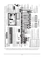
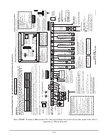
Vista-32FBPT Commercial/Residential Fire and Burglary, Mercantile/Bank Safe and Vault, Local and Police Station,
Central Station and Proprietary Protected Premises Control Unit with DACT Applications Wiring Diagram
Summary of Contents for VISTA-32FBPT
Page 2: ......
Page 62: ...62 ...
Page 64: ...64 ...
Page 84: ...84 ...
Page 88: ...88 ...
Page 94: ...94 ...
Page 100: ...100 NOTES ...
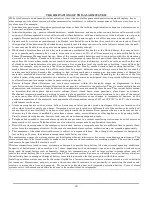
Page 101: ...101 NOTES ...


