background image


50


The 4286 VIP Module features: 


Allows the user to receive synthesized voice messages over the phone regarding the status of the security system. 


Allows the user to arm and disarm the security system and perform most other commands using the telephone 
keypad. 


Allows the user to control relays using the telephone keypad. 


Provides voice annunciation over the phone to confirm any command that is entered.  


Announces many of the same words that would normally be displayed on an alpha keypad under the same system 
conditions.  Refer to the words in bold on the Alpha Vocabulary list found in the 

#93 Menu Mode Programming

 in 

the 

Programming Guide


Can be supervised for connection to control panel (annunciated and reported as Zone 804). 

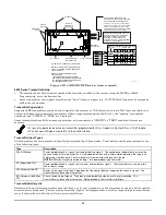
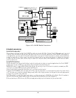
The 4286 is wired between the control panel and the premises’ handset(s) (see 

Figure 3-27

).  It listens for TouchTones on 

the phone line and reports them to the control panel.  During on-premises phone access, it powers the premises phones; 
during off-premises phone access, it seizes the line from the premises phones and any answering machines. 


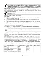
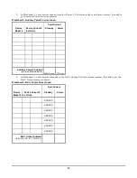
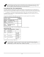
  The VIP module will not operate until the device address (04) is enabled in the control’s 

Device Programming

 in 

#93 Menu Mode

  Do not mount the VIP Module on the cabinet door or attempt to attach it to the PC board. 


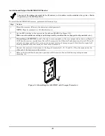
To install the VIP module, perform the following steps: 


Step


Action 

Mount the module in the control cabinet if space is available or, if this is not possible, on the side of the cabinet 
or adjacent to it. 

If you mount the VIP Module inside the control cabinet, 

attach it to the cabinet’s interior surface with 

2-faced adhesive tape.  You may leave the module’s cover off if it is mounted within the cabinet. 

If you mount the module outside the cabinet, 

use the screw holes at the rear to mount horizontally or 

vertically (2-faced adhesive tape may be used, if preferred). 

Affix the 4286 connections


label (supplied separately) to the inside of the VIP Module’s cover, if the cover is 

used. Otherwise, affix the label to the inside of the 

control cabinet’s 

door. 

Make 12V (+) and (–) and data-in and data-out connections from the VIP Module to the control, using the 
connector cable supplied with the VIP Module. These are the same connections as for remote keypads. 

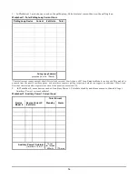
Connect the module to the phone line as shown below. See 

Figure 3-27. 


4286 Terminal 

Connects to:


1.

 Phone In (Tip) 

green wire of direct-connect cord 


2. 

Phone In (Ring) 

red wire of direct-connect cord


3.

 Phone Out (Tip) 

brown wire of direct-connect cord 


4. 

Phone Out (Ring) 

gray wire of direct-connect cord 


5.

 No Connection 


6. 

Audio Out 1* 

Speaker 


7. 

Audio Out 1* 

Speaker 


*Supported by the 4286 only


Use an RJ31X Jack with the phone cable to make connections to the VIP module.  Make connections exactly as 
shown in 

Figure 3-27

.  This is essential, even if the system is not connected to a central station.  The 4286 will 

not function if this is not done.   


  If touch-tones are not present following phone access to the security system 

via an on-premises phone

, try 

reversing the pair of wires connected to terminals 3 and 4 on the 4286. 

  If the phone plug is disconnected from the control, the premise’s phones will not operate. 

Summary of Contents for VISTA-32FBPT

Page 1: ...n n n n n n ne e e e e e e ed d d d d d d d S S S S S S S Se e e e e e e ec c c c c c c cu u u u u u u ur r r r r r r ri i i i i i i it t t t t t t ty y y y y y y y S S S S S S S Sy y y y y y y ys s s s s s s st t t t t t t te e e e e e e em m m m m m m m w w w w w w w wi i i i i i i it t t t t t t th h h h h h h h S S S S S S S Sc c c c c c c ch h h h h h h he e e e e e e ed d d d d d d du u u u ...

Page 2: ......

Page 3: ... Control in the Attack Proof Cabinet Suitable for Commercial Fire Commercial Burglary Applications 23 Installing the Keypads 25 Installing External Sounders 27 Auxiliary Relay Connections 30 Telephone Line Connections 31 Main Dialer Connections 32 Wiring Burglary and Panic Devices to Zones 1 8 33 Installing V Plex Devices 36 Wireless Zone Expansion 39 Installing Output Devices 42 Installing a Remo...

Page 4: ...t 71 Testing Wireless Transmitters 71 Trouble Conditions 72 To the Installer 73 Section 8 Using the Vista 32FBPT as a Slave Communicator 75 Wiring 75 Programming 75 Sending Vista 32FBPT System Troubles to the Fire Alarm Panel 76 Appendix A Regulatory Agency Statements 77 UL Installation Requirements 77 UL864 NFPA Local Fire 77 UL864 NFPA Central Station and Remote Station Fire 77 Commercial Burgla...

Page 5: ... 17 and 18 34 Figure 3 13 4 Wire Smoke Detectors 35 Figure 3 14 Wiring a Normally Closed Sensor Loop for Tamper Supervision 36 Figure 3 15 Wiring a Normally Open Sensor Loop for Tamper Supervision 36 Figure 3 16 Polling Loop Connections to the Control Panel 37 Figure 3 17 Polling Loop Connections Using One 4297 Extender Module 38 Figure 3 18 Polling Loop Connections Using Multiple Extender Modules...

Page 6: ...es This symbol indicates a critical note that could seriously affect the operation of the system or could cause damage to the system Please read each warning carefully This symbol also denotes warnings about physical harm to the user ZONE PROG 1 YES 0 NO 0 Many system options are programmed in an interactive mode by responding to alpha keypad display prompts These prompts are shown in a single lin...

Page 7: ...E TO USERS INSTALLERS AUTHORITIES HAVING JURISDICTION AND OTHER INVOLVED PARTIES This product incorporates field programmable software In order for the product to comply with the requirements in the Standard for Control Units and Accessories for Fire Alarm Systems UL 864 certain programming features or options must be limited to specific values or not used at all as indicated below Program feature...

Page 8: ... Y 0 no 1 yes Must be set to 1 yes 1 13 SYS SENSOR REV RELAY N 0 use neither Zone 1 or Zone 2 inputs 1 use Zone 1 input 2 use Zone 2 input 3 use Zone 1 and Zone 2 inputs Not Used Must be set to 0 1 18 AFFECTS LOBBY PARTITION SPECIFIC N 0 disable 1 enable Must be set to 0 disabled for partition 1 1 19 ARMS LOBBY PARTITION SPECIFIC N 0 disable 1 enable Must be set to 0 disabled for partition 1 1 22 ...

Page 9: ...CESS RELAY PARTITION SPECIFIC N 01 96 relay number 00 relay not used Must be set to 00 relay not used for partition 1 1 78 EXT HOME CONTROL EVT N 1 extended 0 limited Not used Must be set to 0 1 79 HOME CONTROL EVENTS N 0 disable 1 enable Not used Must be set to 0 in each entry 1 80 LOG FAULTS RESTORES N 0 disable 1 enable Not used Must be set to 0 2 07AUTO DISARM DELAY PARTITION SPECIFIC N 00 no ...

Page 10: ...Enter 01 15 multiplied by 2 minutes 00 no timeout Must be set to 3 Minimum of 6 minutes 3 82 BURG FEATURES ENABLED N 0 disable 1 enable Must be set to 0 disable RESTRICTION FOR FIRE RELAYS Y Yes No Restriction for 70 must be set to Yes when programming fire relays Programming Field Settings for ULC304 Compliance NOTICE TO USERS INSTALLERS AUTHORITIES HAVING JURISDICTION AND OTHER INVOLVED PARTIES ...

Page 11: ...ireless zones fewer if using hardwire and or polling loop zones ULC Wireless devices are not ULC Listed and cannot be used in ULC Installations Peripheral Devices Supports up to 31 addressable devices keypads RF receivers relay modules etc Supervises devices keypads RF receivers and relay modules and individual relays up to 32 as well as system zones Keypads 6160CR2 keypads for Fire applications 6...

Page 12: ... Can be armed in one of three STAY modes or Instant modes automatically bypassing specific burglary zones regardless of the zone response type Can automatically bypass specific zones if no one exits the premises after arming Auto STAY Auto STAY will not occur if the system is armed via an RF transmitter VIP module scheduling access control keyswitch or downloading Can bypass a group of zones with ...

Page 13: ...on is restored the queue will be cleared Downloading Supports upload and download capability Downloading must be site initiated for Commercial Fire installations Can periodically and automatically perform a scheduled download UL Remote downloading is not permitted in UL installations A technician must be on site in order to test the system after any system programming is changed Event Log Provides...

Page 14: ...es two style Y supervised Special Application Notification Appliance Circuits Supervision of Notification Appliance Circuits phone lines keypads RF receivers and output devices Provides an auxiliary relay form C that can activate alarms troubles supervisories reset 4 wire smoke detectors or as a battery saver removes power from non critical loads 4 hours after AC power loss Provides up to 60 insta...

Page 15: ... Commercial Fire installations the primary keypad must be connected to Keypad Port 2 mounted within 20 feet of the control panel and wired in conduit Synchronization is required on devices connected to an individual alarm output Each NAC can have its own synchronization module in order to synchronize devices on that output and those devices should be located in the same visual audible area No sync...

Page 16: ...TES 1 2 3 29 28 BLACK RED YELLOW DATA GREEN DATA COMMUNICATORS 4204CF RF RECEIVER DO NOT CONNECT IF USING OPTIONAL AUX POWER BLACK RED BLACK RED BLACK RED YELLOW DATA GREEN DATA BLACK RED YELLOW DATA GREEN DATA 4190SN 4193SN BLACK RED 4101SN 5193SDT 4208SN 4208SNF 4208U 4204 BURGLARY KEYPAD 6160 VPLEX VSI OUTPUT POLLING INPUT POLLING PIR BLACK RED BLACK RED 4193 4208SN 4208U 11 12 13 14 VISTA 32FB...

Page 17: ...partition multiple access can log on to one partition from another partition s keypad provided that program field 2 18 Enable GOTO is enabled for each partition he she wants to log on to from another A partition can be selected as a common lobby partition and other partitions can affect this partition by causing arming disarming of this partition to be automated see Common Lobby Logic later in thi...

Page 18: ... TO ARM LOBBY PARTITION is displayed You cannot select a partition to arm the lobby unless it has first been selected to affect the lobby Do not enable field 1 19 without enabling field 1 18 The following chart sums up how the common lobby partition will operate 1 18 Affects Lobby 1 19 Arms Lobby Disarms when partition disarms Attempts to arm when partition arms Can be armed if other partitions di...

Page 19: ...ed by fields 1 18 and 1 19 Other Methods of Arming Disarming Common Lobby logic remains active when arming or disarming a partition that affects and or arms the common lobby in one of the following manners Quick Arm Keyswitch Wireless Button Wireless Keypad Arming Disarming Remotely If a user arms or disarms remotely through Compass downloading software the lobby does not automatically follow anot...

Page 20: ... if all partitions have been armed successfully The Ready LED is lit only if all partitions are ready to arm Neither LED is lit if only some partitions are armed and or only some partitions are ready Press 0 or 3 to return to the master partition Otherwise if no keys are pressed for 2 minutes the system automatically returns to the master partition The sounder on a Master keypad reflects the sound...

Page 21: ...on 1 Remove the cabinet door and the lock knockout from the door Insert the key into the lock see Figure 3 1 2 Position the lock in the hole making certain that the latch will make contact with the latch bracket when the door is closed 3 When correctly positioned push the lock until its snap tabs hold it securely Use a Honeywell No K4445 Lock supplied CABINET DOOR BOTTOM LOCKED UNLOCKED cab_lock_s...

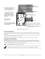
Page 22: ...f the mounting plate Figure 3 3 Detail A Insert the top of the circuit board onto the two standoffs at the top of the mounting plate 2 Place the board flat and secure to the mounting plate with the three accompanying screws and spacers as shown Detail B NOTES Make sure that the mounting screws are tight This ensures that there is a good ground connection between the PC board and the cabinet Dress ...

Page 23: ...ck proof cabinet may be used Mercantile Premises Listing Guidelines The panel door must be supervised Mount the clip on tamper switch supplied to the cabinet s right side wall and wire it to zone 6 Assign zone 6 to a burglary partition Program it for day trouble night alarm zone type 5 when only one burglary partition is used Program it for 24 hr audible alarm zone type 7 when more than one burgla...

Page 24: ...H 6 4 mm Figure 3 5 Commercial Fire Installation Using Attack Proof Cabinet Installing the Control s Circuit Board To install the circuit board in the cabinet perform the following steps Step Action 1 Confirm the Mounting Plate is installed securely in the cabinet Figure 3 6 Detail A Install the nylon standoffs supplied into the top corner holes of the mounting plate Detail B Insert the top of the...

Page 25: ...merun back to the control must not exceed the lengths listed in the table 3 Run field wiring from the control to the keypads using standard 4 conductor cable of the wire gauge determined in step 1 4 Connect keypad s to terminals 11 12 13 and 14 on the control board see Figure 3 7 NOTE In a Fire Application and when using only one keypad it must be connected to Keypad Port 2 and must be mounted wit...

Page 26: ...Y Yellow G Green Y Yellow G Green Figure 3 8 ECP Isolator Wiring Addressing the Keypads The keypads will not operate until they are physically addressed and enabled in the system s Device Programming in the 93 Menu Mode Set each keypad for an individual address 00 30 according to the keypad s instructions Set an alpha keypad for address 00 and other keypads for higher addresses 00 and 01 are enabl...

Page 27: ...N GRN YEL GRN TO KEYPAD BLK WIRE TO KEYPAD RED WIRE TO KEYPAD GRN WIRE TO KEYPAD YEL WIRE pwr_sup_conn 010 V0 TO BURG DEVICES TO FIRE DEVICES TO BURG DEVICES BURG DEVICES FIRE DEVICES TO FIRE DEVICES ECP ISOLATOR OUT IN Figure 3 9 Using a Supplementary Power Supply Installing External Sounders The VISTA 32FBPT provides two Notification Appliance Circuits for operating fire and burglary alarm notif...

Page 28: ...c Module if more than one device is used Follow instructions provided with Sync Module Be sure to use the compatible Sync Module for the Alarm Indicating Device selected MANUFACTURER SYNC MODULE MODEL NUMBER GENTEX AVSM SYSTEM SENSOR MDL WHEELOCK DSM UL All visual notification appliances within the same physical area must be synchronized The bell outputs are listed as Special Application Notificat...

Page 29: ...ll Mount Strobe 12 24V High Candela Red Outdoor SYSTEM SENSOR SRHK Wall Mount Strobe 12 24V Standard Candela White SYSTEM SENSOR SW Wall Mount Strobe 12 24V High Candela White SYSTEM SENSOR SWH Ceiling Mount Strobe 12 24V Standard Candela Red SYSTEM SENSOR SCR Ceiling Mount Strobe 12 24V High Candela Red SYSTEM SENSOR SCRH Ceiling Mount Strobe 12 24V Standard Candela Red Outdoor SYSTEM SENSOR SCRK...

Page 30: ...ral High 10 System Sensor Strobe12 24V SCW 15 Temporal High 10 System Sensor Strobe12 24V SCWH 15 Temporal High 10 Wheelock Horn Strobe 12V 4W MT 121575W 15 Continuous Hi 4 Wheelock Horn Strobe 12V 2W AS 121575W 15 Continuous Hi 6 Wheelock Strobe 12V RSS 121575W 15 na 6 Wheelock Horn Strobe 12V 2W NS 121575W 15 Hi 7 Wheelock Horn 12V 24V NH 12 24 na Hi 80 Wheelock Horn 12V AH 12 na Hi 9 Wheelock H...

Page 31: ... 1 8 and polling loop zones allowing the detectors to be reset Power to the detectors should be wired to the auxiliary relay and to Aux Power 1 output see Figure 3 11 Battery Saver 3 61 3 When this option is selected the auxiliary relay is normally activated e g N O and pole contacts are connected and de activates 4 hours after the start of AC Loss Using this feature non critical loads such as sup...

Page 32: ...M PC board Telephone Line Supervision If the tip ring voltage falls below approximately 25 volts 13 volts if the blue jumper is cut or the handset current is less than approximately 10mA the supervision circuits for the dialer output will indicate a fault condition Faults on the phone lines are displayed as zones 974 main dialer and 975 backup dialer To prevent risk of shock disconnect the phone l...

Page 33: ...esistor must be connected across the loop wires at the last device Using 2 Wire Smoke Detectors on Zones 1 and 2 Zone 1 and 2 can support up to 16 2 wire smoke detectors each 32 total The alarm current on zones 1 and 2 supports only one smoke detector in the alarmed state When assigned zone type 9 or 16 the second entry of a User Code off at a keypad interrupts power to these zones to allow detect...

Page 34: ...an alarm and therefore must be momentarily interrupted using the auxiliary relay Compatible 4 Wire Smoke Detectors Use any UL Listed 4 wire smoke detector that is rated for 12VDC operation and that has alarm reset time not exceeding 6 seconds Some compatible 4 wire smoke detectors are listed below DETECTOR TYPE MANUFACTURER MODEL 4 Wire Photoelectric Smoke Detector DSC FSA 410B 4 Wire Photoelectri...

Page 35: ... Tamper Configuration Zone 6 may be used as a tamper loop for the VISTA 32FBPT Cabinet Door Tamper Switch Assign zone 6 to a burglary partition Program it for day trouble night alarm zone type 5 when only one burglary partition is used Program it for 24 hr audible alarm zone type 7 when more than one burglary partition is used Enable the Zone 6 Alternate Tamper Function program field 3 17 Tamper S...

Page 36: ...e control panel in a star configuration If a module is using optional aux power do not connect the polling loop terminal to the device Use the ground from the power source 1 Do not run polling loop wires within 6 of AC power telephone or intercom wiring The polling loop is carrying data between the control panel and the devices interference on this loop can cause an interruption of this communicat...

Page 37: ...e if required Refer to the device s instructions for the DIP Switch Tables 3 Mount each device in the desired location Refer to the device s instructions 4 Run wires from the control panel to each device on the polling loop see Figure 3 16 No individual wire run may exceed the lengths shown in the following table Maximum Polling Loop Wire Runs Wire Gauge Max Length 22 gauge 650 feet 20 gauge 950 f...

Page 38: ...NGTH 22 650 FT 20 950 FT 18 1500 FT 16 2400 FT NO MORE THAN119 DEVICES COMBINED TOTAL LENGTH OF ALL WIRE RUNS ON BOTH LOOPS COMBINED CANNOT EXCEED 6400 FT 3200 FT IF USING UNSHIELDED WIRE IN CONDUIT OR IF USING SHIELDED WIRE polling_loop_003 V4 COMBINED INPUT AND EXTENSION LOOP LIMITS V PLEX DEVICE V PLEX DEVICE DO NOT CONNECT Figure 3 17 Polling Loop Connections Using One 4297 Extender Module INP...

Page 39: ...ns front and back tampers that permit its use in commercial burglary installations You may only mount the 5881ENHC its own plastic housing Otherwise the receiver constantly reports a tamper condition The control checks the receiver connections about every 20 seconds The receiver supervisory zone is 8 2 digit receiver device address for example Device address 05 supervisory zone 805 NOTE This zone ...

Page 40: ... module etc 3 If installing a 5881ENHC install a flat head screw supplied in the case tamper tab as shown in Figure 3 20 When the receiver is pried from the wall the tamper tab will break off and remain on the wall This will activate a tamper switch in the receiver and cause generation of a tamper signal Note that this signal will also be generated when the receiver s front cover is removed 4 Conn...

Page 41: ...itter within a programmed period field 1 31 the missing transmitter number s and CHECK or TRBL are displayed Some transmitters have built in tamper protection and annunciate a CHECK or TRBL condition if covers are removed If a loss of supervision occurs on a transmitter programmed for Fire it reports in Contact ID as a Fire Trouble 373 not Loss of Supervision 381 to the central station Transmitter...

Page 42: ... module provides 4 relays with Form C normally open and normally closed contacts Each 4204CF module adds two style Y supervised Notification Appliance Circuits to the system For 4204CF modules only relays 1 or 3 on each module can be programmed 4204 and 4204CF relays may be used to trigger auxiliary fire functions such as air handler shutdown elevator recall door holder release sound system shutdo...

Page 43: ...WITCH FOR SETTING DEVICE ADDRESS AND ENABLING DISABLING TAMPER 4 PIN CONSOLE PLUG 12VDC SUPPLIES POWER TO MODULE CIRCUITRY INCLUDING APPLIANCE OUTPUT RELAY COILS CURRENT DRAIN AT 12V IS 25mA 80mA PER ACTIVE OUTPUT DATA IN FROM CONTROL DATA OUT TO CONTROL GROUND POLARIZED NOTIFICATION APPLIANCES NOTIFICATION APPLIANCE OUTPUT B 2K EOLR EOL20 NOTIFICATION APPLIANCE OUTPUT A 2K EOLR EOL20 4204CF 4204C...

Page 44: ... 05 Operation A momentary short arms the partition in the AWAY mode and a short held for more than 10 seconds arms the partition in STAY mode 1 A subsequent short disarms the partition The keyswitch LEDs indicate the partition s status see table that follows A momentary short silences Notification Appliance Circuits and keypad sounds and disarms the system if it was armed A subsequent short clears...

Page 45: ...8N Piezo Sounder can be used to duplicate the sounds produced by the keypad s built in sounder The remote sounder will duplicate all sounds such as alarms trouble beeps etc except for the short beeps associated with keypad key depression One application of this feature would be to produce chime beeps at a distant location from the keypads If used program field 3 20 must be set to 0 and field 15 mu...

Page 46: ...Signaling feature functions If Priority 57 is And message is Then Primary Phone No 0 Acknowledged before delay expires Message is removed from queue and no message is sent to communications device Not acknowledged before delay expires Message is sent to both the Primary Phone No and communications device Communicator 1 Acknowledged before delay expires Message is removed from queue and no message ...

Page 47: ... they are secure factory service is required All these messages are displayed in conjunction with the CHECK 8xx message which indicates a trouble on the address to which the communications device is programmed in the control All of these events except Antenna Fault are sent to the event log and reported to the central station using Contact ID Event Code 333 expansion device trouble Antenna Fault u...

Page 48: ...round leads to terminals 2 5 and 9 b The DSM optional RTE and General Purpose leads to terminals 6 7 and 8 respectively c Door strike or mag lock lead to terminal 10 d Local 12V or 24V supply lead to terminal 1 e Local 12V or 24V supply lead to the N C relay terminal 11 if a mag lock is being used OR to the N O relay terminal 10 if a door strike is being used 5 Connect the polling loop and polling...

Page 49: ...TECTION ASSOCIATION S STANDARDS 70 74 NATIONAL FIRE PROTECTION ASSOC BATTERYMARCH PARK QUINCY MA 02269 PRINTED INFORMATION DESCRIBING PROPER MAINTENANCE EVACUATION PLANNING AND REPAIR SERVICE IS TO BE PROVIDED WITH THIS EQUIPMENT TO TB1 11 OR 12 12 VDC TO ONLY ONE OF THESE INPUTS FROM TB1 1 Figure 3 26 Wiring the VistaKey Event Log Connections This system has the ability to record up to 512 events...

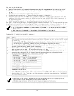
Page 50: ...et or adjacent to it If you mount the VIP Module inside the control cabinet attach it to the cabinet s interior surface with 2 faced adhesive tape You may leave the module s cover off if it is mounted within the cabinet If you mount the module outside the cabinet use the screw holes at the rear to mount horizontally or vertically 2 faced adhesive tape may be used if preferred 2 Affix the 4286 conn...

Page 51: ...on Vista 32FBPT Depending on your application you may need to adjust the configuration of your printer home automation system or external software package to match the new faster speed Consult the documentation for your external hardware or software for directions on how to do this In some cases you may need to contact the vendor of this external hardware or software for an update patch or new dri...

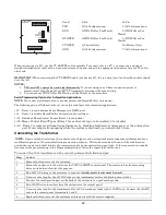
Page 52: ...rol Event Types Enter 1 for each event type to be enabled 0 to disable 1 80 Enter 1 to improve automation performance by disabling fault restore messages over the automation port If you require live mapping while the system is disarmed you must enter 0 here Connecting the Transformer NOTE Upon a total power failure the control unit will ignore and not transmit alarm supervisory information for a s...

Page 53: ...ery must be connected the control panel ULC For ULC Commercial Fire Installations only the 34 4AH 2 x 17 2AH batteries have been evaluated For ULC Commercial Fire Installations the batteries capacity must be sized for 24 hour Standby followed by a 30 minute Alarm If a Commercial Fire Listed 24VDC Power Supply is used refer to its Installation Instructions for the appropriate backup battery require...

Page 54: ...This module is powered from the panel s auxiliary power and provides a separate polling loop output which can support an additional 128mA load Note that the total number of points connected to the panel cannot exceed 119 2 In Worksheet 2 enter devices used on Auxiliary Power 1 Calculate standby and alarm currents then add to get Auxiliary Power 1 current subtotal Worksheet 2 Auxiliary Power 1 Curr...

Page 55: ... X of Units Standby Alarm Auxiliary Power 2 Subtotal pin 5 on keypad port 2 400mA max 1 7A max 4 In Worksheet 4 enter devices connected to the Bell 1 Output Calculate alarm currents then add to get the Bell 1 Output current subtotal Worksheet 4 Bell 1 Output Current Load Total Current Device Model Device Current X of Units Standby Alarm XXXXXX XXXXXX XXXXXX XXXXXX XXXXXX XXXXXX XXXXXX Bell 1 Outpu...

Page 56: ...he combined current Worksheet 6 Total VISTA 32FBPT Current Load Total Current Standby Alarm Polling Loop Subtotal Auxiliary Power 1 Subtotal Auxiliary Power 2 Subtotal Bell 1 Output Subtotal Bell 2 Output Subtotal VISTA 32FBPT PCB Current Incl 2 wire smoke detector loading on zones 1 2 300mA 470mA 5140DLM Backup Dialer Module 5mA inactive 15mA active Total Current Load 1A max standby 2 3A max alar...

Page 57: ...es to be wired in parallel for increased capacity Using the total calculated from Worksheet 6 calculate the battery capacity required for the installation Worksheet 7 Battery Capacity Calculation Worksheet Capacity Formula Calculated Value Standby Capacity Total standby current X 24 hours X 1 1 contingency factor Alarm Capacity Total alarm curr X 0 083 5 min or X 0 250 15 min Total Capacity Add st...

Page 58: ...ATTERIES IN PARALLEL USE BATTERIES FROM THE SAME MANUFACTURER AND WITH THE SAME VOLTAGE AND CAPACITY RATING USE BATTERIES WITH APPROXIMATELY SAME AGE AND STATE OF CHARGE USE CABLES PROVIDED AND OBSERVE POLARITY IT IS RECOMMENDED THAT ALL BATTERIES BE REPLACED AT SAME TIME EVEN IF ONLY ONE BATTERY HAS BECOME WEAK AS LONG AS ONE GOOD BATTERY REMAINS CONNECTED THE ONCE PER 60 SECOND BATTERY TEST WILL...

Page 59: ...l 1 2 or higher internal level 1 1 or higher Hayes Optima 24 Fax 96 external Hayes Optima 336 BizComp Intellimodem 1200 w volume BizComp Intellimodem 2400 Other brands are not compatible even if claimed to be 100 compatible Internal modems must have a 4 position DIP switch Modems with a 6 position DIP switch will not work 1 Compass revision 2 0 xx or above IP GSM Downloading Panels can be download...

Page 60: ...ds the control processes the request making sure certain encrypted information received from the computer matches its own memory 5 Upon a successful match the control panel seizes the phone line and calls the computer back unless callback is not required The phone number to which the computer s modem is connected must be programmed into the control field 35 6 The computer answers usually by the se...

Page 61: ... and ECP equipment list Set the real time clock Direct Wire Downloading The VISTA 32FBPT can be downloaded without using a modem or telephone line The direct wire downloading connection is to be temporary and is not part of the permanent installation Direct wire downloading is meant as a tool for the installer during the installation process Telco Handoff Telco handoff is another method of getting...

Page 62: ...62 ...

Page 63: ...sed on the date entered Time and date entries are made by simply entering the appropriate hour minute month day and year Press to move the cursor to the right of the display to the next position Press to move the cursor to the left of the display to the previous position 2 Enter the correct hour Then press to move to the minutes field 3 Enter the correct minutes Press to move to the AM PM position...

Page 64: ...64 ...

Page 65: ...ar user is authorized These levels are described below Level 0 Installer User 1 Code Programmed in field 00 default 5 1 4 0 Installer Open Close reporting selected in field 39 Can perform all system functions arm disarm bypass etc but cannot disarm if armed by another code or by Quick Arm Can add delete or change all other codes and can select Open Close reports for any user Is the only code that ...

Page 66: ...ly from within the partition it was created in User numbers must be entered in 2 digits Single digit user numbers must therefore always be preceded by a 0 e g 03 04 05 etc Make sure the end user understands this requirement Temporary codes are entered as 4 digit numbers Open Close Reporting Note When a user is added the system prompts for Open Close reporting capability only if the installer is ad...

Page 67: ...el Enter the level number as follows 1 Master 2 Manager 3 Operator A 4 Operator B 5 Operator C 6 Duress Keypad then prompts for Open Close reporting option for this user Open Close Rep 0 NO 1 YES Press 0 NO or 1 YES depending on whether or not arming disarming by this user will trigger Opening and Closing reports This prompt appears only if the Installer Code is used to add a user Group Bypassing ...

Page 68: ...tes the partition from which the user may be changed or deleted Changing a Master Manager or Operator Code Enter Installer Code 8 new user no 02 75 new user s code Or Master or Manager Code but the code must be a higher level of authority than the code being changed e g a Manager Code can add an Operator level Code but cannot add a Master or another Manager Code PROMPT EXPLANATION User Number 03 N...

Page 69: ... The system continues to monitor all 24 hour type zones fire panic etc and ends the test if any of these zone types produce an alarm condition This test should be conducted at periodic intervals as determined by the local authority having jurisdiction One Man Fire Walk Test Code 68 This test causes the system to sound console beeps and Notification Appliance Circuit dings in response to fire zone ...

Page 70: ...pliance Circuits to ding The keypads will display the zone number and the associated alpha descriptor while the zone remains faulted The system automatically issues a smoke detector power reset about 10 seconds after it finds a fault on one of these zones to allow faulted detectors to be reset The system will automatically perform the smoke detector reset on zones 1 and 2 if programmed for fire an...

Page 71: ...security code and pressing OFF If the system has been programmed for silent panic there are no audible alarms or displays A report is sent to the central station however 8 Notify the central station that all tests are finished and verify results with them Testing Wireless Transmitters Transmitter ID Sniffer Mode Use the Transmitter Sniffer Mode to test that transmitters have all been properly prog...

Page 72: ...cover removed CHECK 6XX XX 01 32 This indicates a trouble on a 4204CF Supervised Notification Appliance Circuit corresponding relay number 01 32 CHECK 8XX XX 00 30 This indicates a trouble on a peripheral device connected to the panel s keypad terminals of the corresponding device address 00 30 CHECK 9XX XX 70 77 88 90 97 This indicates that a system trouble exists RF receiver Notification Applian...

Page 73: ...aler line Earth ground fault Bypass of earth ground supervisory zone Fault on LORRA XMIT OK signal if enabled LORRA trigger bypassed AC failure Low system battery Keypad supervision fault The Off Normal report is sent as follows Contact ID Code 608 Express Speed Digits programmed in System Group 4 report codes To the Installer Regular maintenance and inspection at least annually by the installer a...

Page 74: ...ere applicable Verify that all keypads and devices are addressed properly Note the proper model number of this product and the version level if known along with any documentation that came with the product Note your Honeywell customer number and or company name Having this information handy will make it easier for us to serve you quickly and effectively Technical Support 1 800 645 7492 8 a m 8 p m...

Page 75: ... on the Vista 32FBPT 5 If using a keypad connected to the Vista 32FBPT and the Communicator will be unmanned program field 77 Auto Restore for option 2 restore troubles and fire alarms 6 If using zone type 18 field 3 13 Fire Supervisory Response to Open Short must be set to 1 to report Supervisory on short or open NOTES 1 Do not use zone type 16 Fire w Verification for the input zone for fire on t...

Page 76: ...rm panel as shown below V32FB 003 V0 4204CF FIRE ALARM PANEL ZONE INPUT N C N O C At the Vista 32FBPT program the each relay in 93 output programming mode to activate on one of these conditions The Start events for these outputs should be programmed as the following Zone Type System Operations 41 AC Power Fail 42 System low battery 43 Communications failure Select the same options for the Stop eve...

Page 77: ...one line Assign a 24 hour trouble response type 19 to system Zone 975 to enable backup dialer supervision 5 When the dialer is used program it to send fire alarm fire supervisory if used trouble AC loss low battery normal dialer test and off normal dialer test reports Field 27 must be set to 024 maximum so that test reports are sent at least once every 24 hours 6 If a secondary number is programme...

Page 78: ... must be of the normally closed circuit fully supervised type Total current load must be 430mA max standby 1 7A max alarm Standby time must be at least 72 hours and 15 minutes To be installed inside the safe or vault UL1610 Central Station Burglary Alarm Follow the instructions for UL365 local installations stated above and follow the additional guidelines below For Systems without Line Security Y...

Page 79: ...sconnect the phone connection inside the control panel Doing so will result in the loss of your phone lines If the regular phone works correctly after the control panel has been disconnected from the phone lines the control panel has a problem and should be returned for repair If upon disconnection of the control panel there is still a problem on the line notify the telephone company that it has a...

Page 80: ... of all the devices does not exceed 5 AVIS L étiquette d Industrie Canada identifie le matériel homologué Cette étiquette certifie que le matériel est conforme aux normes de protection d exploitation et de sécurité des réseaux de télécommunications comme le prescrivent les documents concernant les exigences techniques relatives au matériel terminal Le Ministère n assure toutefois pas que le matéri...

Page 81: ...r Only Transmitter ID Test Code 3 Installer Only Go No Go Test Code 5 Test Key Additional Commands Partition GOTO User Code Partition Number 0 2 GOTO Home Partition User Code 0 Panics 1 or A Key Zone 995 or B Key Zone 999 3 or C Key Zone 996 View Downloaded Messages Press 0 for 5 Seconds Display All Zone Descriptors Press for 5 Seconds Display User Self Help Hold Any Key for 5 Seconds Output Devic...

Page 82: ...Device Programming User Code 83 Relay Control Commands Activate Relay for Current Partition User Code 0 Access Control Commands Activate Access Relay for Current Partition User Code 0 Request to Enter Exit User Code 73 Request to Enter Exit at Access Point User Code 74 Access Point Number Change Access Point State User Code 75 Access Point State Perform a Test of the VistaKey Module Installer Code...

Page 83: ...O Contact ID ADEMCO 10 Digit Contact ID and 4 2 Express Compatible Receivers 7810iR ent MX8000 5140DLM BACKUP DIALER MODULE Physical 2 75 H X 4 W X 1 D Mounts on VISTA 32FBPT main PC board shield using standoffs supplied Connects to VISTA 32FBPT main PC board J3 header using ribbon cable supplied FCC Registration AC3 USA 62628 MO N UL ULC Listings Standard No Name Edition UL864 Control Units and A...

Page 84: ...84 ...

Page 85: ...upervision RF 382 Loss of V Plex Supervision 383 V Plex Sensor Tamper 384 RF Transmitter Low Battery 385 High Sensitivity Maintenance Signal Code Definition 386 Low Sensitivity Maintenance Signal 389 Detector Self Test Failed 401 O C by User 403 Power Up Armed Auto Arm 406 Cancel by User 407 Remote Arm Disarm Download 408 Quick Arm 409 Keyswitch O C 411 Callback Requested 421 Access Denied 422 Acc...

Page 86: ...der Module Trouble RF TRBL RF Trouble TAMPER Tamper FIRE TRB Fire Trouble FAIL TO COMM Failure to Communicate BELL TROUBLE Bell Trouble DISARMED Disarmed DISARMED REM Disarmed Remotely DISARMED KEY Disarmed Via RF Key DISARM AUTO Auto Disarm CALL BACK Callback Requested CANCEL Cancel DISRMD EARLY Disarmed Early DISRMD LATE Disarmed Late MISSED DISRM Missed Disarm SKED CHANGE Schedule Change ACC SK...

Page 87: ...o Module RES MOD Access Control Module Reset ACPT RLY Access Point Relay Supervision Fail SELF MOD Module Self Test Failure ACZN CHG Access Control Zone Change ACS PROG Access Control Program Entry ACS PRGX Access Control Program Exit THRT CHG Access Control Threat Change SYS SHUT System Shutdown SYS RST System Engineer Reset ZN SHUNT Access Control Zone Shunt ZN ALARM Access Control Zone Alarm RD...

Page 88: ...88 ...

Page 89: ...way Mode All Vista Control Panel have the ability to arm Away This will arm all perimeter and interior zones AWG Average Wire Gauge the standard by which wire is measured wire thickness in millimeters Standard in the alarm industry is 22awg B Backlighting Refers to the lighting up of the keypad s keys and or display screen Battery Calculations To meet certain UL regulations the system battery must...

Page 90: ... End of Line Supervision Relay Relay used to supervise the power on 4 wire smoke detectors Event Log In some controls events can be stored for later viewing Events Event Log Types Events Situations that have occurred i e Alarms Troubles Arming Disarming etc Event Log Types The event log stores events in many categories such as Alarms Checks troubles Bypasses Open Close Disarm Arm System loss of ac...

Page 91: ...00 series transmitters and V Plex Serial Poll devices send unique serial numbers that are learned for that zone Limited Access Some controls may be programmed to allow certain codes to only work during certain times see also Access schedules Line Fault Term used to describe the loss of telephone line voltage M M E A Material Evaluation Authority agency listing for commercial fire installations in ...

Page 92: ...n a circuit Relay Module An addressable module used on some controls 4204 4229 or 4101SN Relay Output Some controls support programmable Relay Outputs these can be 4204 4229 or 4101SN Report Code The alpha numeric report that is transmitted to the central station receiver to identify the events that have occurred Report Format The Language in which an alarm report is set to the central station Res...

Page 93: ...panel to the computer User Code a k a Access code Security Code Always 4 digits V V I P Abbreviation for Voice interactive Phone Module 4286 Vista A line of Honeywell Panels W Wireless a k a RF Refers to the 5800 5700 series wireless transmitters and receivers Wireless Button A 5800 Series Transmitter that employs buttons such as a pendant or wireless key fob Wireless Keys 5804 series Keyfobs A mi...

Page 94: ...94 ...

Page 95: ...ery Test 71 Bell 1 Output Current Load 54 Bell 2 Output Current Load 55 Bell Output Supervision 27 Burglary Walk Test 72 Button RF 40 C Callback 61 Callback Requested 60 CANADIAN EMISSIONS STATEMENTS 80 Changing a User Code 68 Check Messages 74 COMM FAILURE 74 Commercial Burglary Requirements 77 Commercial Fire Guidelines 23 Common Lobby 17 Communicators Connected to ECP 45 COMPASS Downloading Sof...

Page 96: ...des Level 2 65 Master Codes Level 1 65 Master Keypad 19 Mercantile Premises Listing 22 Mercantile Safe and Vault Listing 22 MODEM COMM 60 75 Modems 59 Mounting The Control Cabinet 21 Multi Access 67 Multiple Partition Access 66 O OPEN CIRCUIT 25 Off Normal Report 75 One Man Walk Test 71 On Line Control Functions 62 Open Close Reporting 66 Operator Access Levels 59 Operator Codes Levels 3 5 66 Outp...

Page 97: ...rning the System Over to the User 75 U UL Installation Requirements 77 UL1610 Central Station Burglary Alarm 78 UL365 Police Station Connected Burglar Alarm 78 UL609 Local Mercantile Premises Local Mercantile Safe Vault 78 UL864 NFPA Central Station and Remote Station Fire 77 UL864 NFPA Local Fire 77 UNABLE TO ARM LOBBY PARTITION 18 Unsupervised RF 40 User Access Codes 65 User Code Authority Level...

Page 98: ...cannot detect motion or intrusion that takes place behind walls ceilings floors closed doors glass partitions glass doors or windows Mechanical tampering masking painting or spraying of any material on the mirrors windows or any part of the optical system can reduce their detection ability Passive Infrared Detectors sense changes in temperature however as the ambient temperature of the protected a...

Page 99: ...99 For the latest warranty information please go to www honeywell com security hsc resources wa ...

Page 100: ...100 NOTES ...

Page 101: ...101 NOTES ...

Page 102: ...econds THE DELAY TIME MARKED ON THE INSTALLED DETECTOR S IS TO BE USED 8 Seconds 8 Seconds 8 Seconds Zone 2 Aux Relay Zone 1 BELL CIRCUIT SUPERVISION JUMPERS DO NOT CUT AUXILIARY POWER 1 1 0A MAX STANDBY For Canada 650mA 1 7A MAX ALARM See Note 1 Max Impedance 0 6 Ohms Special Application Circuit Fire Burglary Devices on the ECP Bus must be isolated using an ECP Isolator Refer to Instructions for ...

Page 103: ...tallation limits under jurisdiction of local authority 2k 2 WIRE SMOKE DETECTOR LOOP N C N O SMOKE 2 WIRE SMOKE DETECTOR LOOP N C N O SMOKE REMOTE KEYPADS 6160 6160CR 2 SEE NOTE 2 Red Blk Grn Yel N C N O N C N O N C N O N C N O 2k 2k ZONE 1 8 NOTES Polling Loop Class B Style 3 Polling Loop Ratings supervised 128mA max See note 1 8 11 VDC 20 Ohms Max Impedance See instructions for compatible device...

Page 104: ...Ê800 11043V1hŠ 800 11043V1 11 12 Rev A 2 Corporate Center Drive Suite 100 P O Box 9040 Melville NY 11747 Copyright 2012 Honeywell International Inc ...

Reviews: