EN1R--9137 9808R6--NE
3
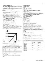
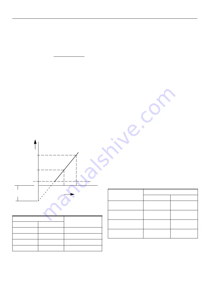
Amplification factor (A) (see fig. 2.)
The amplification factor (A) is defined with the positive air sig-
nal connected to the gas/air module.
With a negative air signal the amplification factor is 1.0 lower
(e.g. 2.5 ... 4 instead of 3.5 ... 5)
Amplification factor (
A
) =
P
outlet 2
-- P
outlet 1
P
air high 2
-- P
air high 1
Formula:
Definitions:
Pressure drop across air restriction = P
air high
-- P
ambient
Pressure drop across gas injector = P
outlet
-- P
ambient
P
air high =
air pressure connected on the positive air side.
P
ambient =
atmospheric pressure (mbar)
P
air high 1 =
air pressure at which the offset is factory adjusted
(depending on O.S. number).
P
air high 2 =
P
air high 1
+ 1 mbar
P
outlet 1 =
outlet pressure at P
air high 1
P
outlet 2 =
outlet pressure at P
air high 2
Fixed amplification (depending on O.S. number)
As specified between 5 and 25 mbar/mbar
Adjustable amplification
The adjustable amplification factor can be adjusted until --30%
from the nominal amplification factor.
The air pressure difference measured on the pressure taps of
the module is reduced with the same factor as the
amplification factor is reduced compared with the actual air
pressure difference.
P
outlet 1
Offset
0
P
outlet
P
outlet 2
P
air high
P
air high 1
P
air high 2
Fig. 2.
Table 1. Adjustable amplification factor
Amplification factor
Minimum outlet
pressure (mbar)
Range
Nominal
pressure (mbar)
3.5 ... 5
5
1.5
7 ... 10
10
2.5
10.5 ... 15
15
3.5
17.5 ... 25
25
5.5
Outlet pressure (P
o
)
Outlet pressure is pressure drop across the main burner
orifice.
Air pressure difference
P
air, high --
P
air, low
Offset
Offset = P
o
-- P
air,high
x A
Offset range
--0.5 x A ... 0.0 x A mbar (depending on O.S. number)
Outlet pressure range
(0.2 x A + 0.5) ... 50 mbar
The minimum outlet pressure (0.2 x A + 0.5) is corresponding
with a typical accuracy of
¦
10% of outlet pressure.
(Depending on O.S. number)
Minimum outlet pressure range
See table 1.
Maximum inlet pressure
60 mbar
Air pressure limitation
--10 ... +10 mbar
Minimum regulation capacity
0.31 m
3
/h air at 1.5 mbar outlet pressure
Maximum outlet pressure adjustment
The maximum outlet pressure adjusment is an optional
feature and the adjusting is depending on O.S. number.
Maximum operating gas pressure
The P
max
60 mbar indication on the housing is the maximum
inlet pressure at which the combination gas control functions
safely.
Capacity
3.4 m
3
/h air at
D
p = 3 mbar
Curves are available on request.
Timing
Closing time:
±
1 s
Opening time:
±
1 s from start of flow till outlet pressure
is 1 mbar.
Mounting holes
Two mounting holes at the bottom for thread forming screws.
Valve classification
Type
Class
1
st
valve
2
nd
valve
VK4105
VK8105
Class B
Class J
VK4115
VK8115
Class B
Class C
VK4135
VK8135
Class A
Class J
VK4145
VK8145
Class A
Class C

