background image

OPERATING INSTRUCTIONS 

VM242A BASICMES-2 


Honeywell • All rights reserved 

MU2H-1054GE25 R0411 

Item 

Spare part 
ordering number 

Carry case with foam insert 

VMS242A007 


2.4


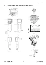
Names of the Components 


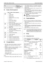
Table 2.  Names of the components 

1 Mode 
2  Time and date 
3 Battery 

status 

4 Measured 

value 

5  Selected valve and valve setting 
6 Menu 

bar 

7  Power on/off / enter key 
8  Line up / line down keys 

See 

Fig. 1 

9  Escape / return key 

10  Screen and keyboard (details see above) 
11  Device housing with rubber padding 

See 

Fig. 2 

12  Cover for hose and temperature sensor 

connections 

13 Battery 

cover 

14  Typeplate and calibration mark (attached 

after first re-calibration) 

See 

Fig. 3 

15  Cover for hose and temperature sensor 

connections 

See 

Fig. 4 

16  Socket for battery charger 

17 Infrared 

transmitter 

See 

Fig. 5 

18 USB 

socket 

19 Socket 

T

1

 for temperature sensor 

20 Socket 

T

2

 for temperature sensor 

21  Connection for high pressure hose 

See 

Fig. 6 

22  Connection for low pressure hose 


2.5


Charging Batteries 


  Plug battery charger into line voltage power socket and 

into power socket on right side of device (see Fig. 4, 

item 16) 

  Batteries are charged. Charging is indicated by a light on 

the battery charger with the following states: 

 Yellow: not connected or initialising 

 Orange: fast charge 

 Green/yellow: top-off charge 

 Green: trickle charge 

 Orange/green: error 

  Full charge of original batteries takes approx. three hours 


NOTE  

  Use dedicated battery charger supplied with device only 

  Charge batteries indoors or in a sheltered environment 

within specified ambient temperature (see data sheet in 

appendix) only 

  Batteries will be exhausted if left for a long period of time 

after being charged 

  Battery charger can be used as mains power supply for 

device, e.g. during data logging, if device is equipped with 

rechargeable batteries 

  Device does not work when not equipped with batteries. 

Also not when battery charger is connected 

WARNING 

Battery charger must NOT be used when device is 

equipped with non rechargeable batteries 


2.6


Replacing Batteries 

 
The lid of the battery compartment is opposite the display. 

  Remove lid by pushing down tab on topside of device and 

sliding lid off 

  Remove old batteries. Pull ribbon to remove lower two 

batteries 

  Insert new batteries. Pay attention to correct polarity as 

indicated in battery compartment. Place ribbon below 

lower batteries 

  Replace lid. Ensure tab snaps back into place 


NOTE:  Instead of rechargeable batteries four standard AA 

size dry batteries can be used alternatively. Never 

try to recharge standard dry batteries. Never mix 

standard dry batteries with rechargeable batteries 


2.7


Setup 


2.7.1


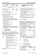
Setting Device Clock 

 
To set or change time and date proceed as follows: 

Operation 

Command 

Key 

Switch on device 

— 

ON 

Device carries out zero calibration and then automatically 

switches to measuring mode


Stop ongoing measurement 

Stop 

ON 

Enter main menu 

Menu 

ESC 

Scroll down to menu item 
“Setup” 

 DOWN 

Enter Setup menu 

Ok 

ON 

“Time” is first item in setup menu 

Move cursor into data field 
until first digit to be changed is 
highlighted 

 ON 

Change value of digit 

↑↓

 UP/DOWN 

Move to next digit 

 ON 

Change value of digit 

↑↓

 UP/DOWN 

Etc., when all changes are done:


Move cursor out of data field 

 ON 

Cursor disappears and new value is stored 

Summary of Contents for VM242A BasicMes-2

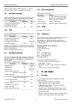
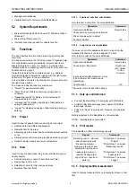
Page 1: ... Direct Input of kv value 5 4 Function overview 5 4 1 How to access the Main Menu 5 4 2 Valve Selection Select valve 5 4 3 Project Function Select project 6 4 4 Flow Measurement Hydr balancing 6 4 5 Temperature Measurement 7 4 6 Leakage Test 7 4 7 Data Logging 7 4 8 DP Measurement 7 4 9 USB Data Exchange 8 4 10 Print 8 4 11 Save Measurements 8 4 12 Data management 8 4 13 Setup 8 4 14 Calibration 8...

Page 2: ...nd adjustment work may only be carried out by authorized persons Immediately rectify any malfunctions which may influence safety WARNING Attention has to be paid when hoses are removed from valve after measuring When quick connection is pulled off remaining hot media may leak presenting danger of scalding CAUTION Media gas water oil do not mix 2 BASIC INFORMATION 2 1 Intended Use The BasicMes 2 ha...

Page 3: ...cified ambient temperature see data sheet in appendix only Batteries will be exhausted if left for a long period of time after being charged Battery charger can be used as mains power supply for device e g during data logging if device is equipped with rechargeable batteries Device does not work when not equipped with batteries Also not when battery charger is connected WARNING Battery charger mus...

Page 4: ... 7 11 Menu bar The following descriptions assume the main screen as starting point 3 1 Flow Measurement using Valve Database Select valve and valve size from device database Compare valve presetting with presetting shown in display of the BasicMes 2 Values must be identical Connect the BasicMes 2 to valve red hose is installed to higher pressure outlet before orifice or valve seat blue hose is ins...

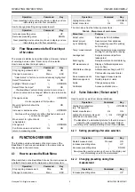
Page 5: ...BasicMes 2 shows the main screen as a default How to access the main menu and a menu item Operation Command Key Stop ongoing measurement Stop ON Change to main menu Menu ESC Operation Command Key Highlight menu item UP DOWN Select menu item Ok ON The main menu has the following menu items Table 4 Menu items of main menu Menu item Purpose Select valve Select valve from database Select project Selec...

Page 6: ...eady been stored for this riser which should not be overwritten Decline to overwrite existing data No ESC Operation Command Key The BasicMes 2 returns to riser selection where either another riser can be selected to store measurement or a new riser can be defined to store measurement or function can be left without storing measurement The measurement stays in the buffer memory of the BasicMes 2 un...

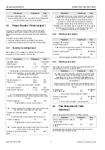
Page 7: ...ge test time with following options Operation Command Key Return to main menu without starting the test Esc ESC Select data field UP DOWN Change data ON The test consists of three parts Switch on and or set pump speed Stabilisation period indicated by a countdown clock Leakage test during which a graph is drawn Operation Command Key Confirm that pump has been switched on and set to correct speed P...

Page 8: ...t overwrite old data No ESC Device returns to riser selection screen Overwrite old data Yes ON Information screen appears Confirm notification Ok ON Device returns to main menu 4 12 Data management Used for following functions Menu item Purpose Print protocol Print measurements saved within a project over optional pocket printer Delete riser Delete single riser of a project Delete project Delete c...

Page 9: ...ign supply and return temperature 5 3 2 Riser Used for input of data concerning a riser distribution pipe or heat consumer Short description or name of riser free text field Design flow in l h or m h Selection of valve for this riser see below Remarks free text field 5 3 2 1 Selection of valve from valve database How to select a valve from the valve database Operation Command Open valve database S...

Page 10: ...options are available Deletion of one certain size Deletion of all sizes of a certain valve type Deletion of all valves of a certain manufacturer Deletion of all valves To delete a valve size valve type manufacturer or all valves from the database right click onto the respective point in the tree structure then click onto the delete option NOTE Deleted elements are immediately erased and cannot be...

Page 11: ...PERATING INSTRUCTIONS VM242A BASICMES 2 Honeywell All rights reserved 11 MU2H 1054GE25 R0411 7 ILLUSTRATIONS ABBILDUNGEN FIGURES FIGURA Fig 1 Fig 2 Fig 3 Fig 4 Fig 5 Fig 6 Fig 7 1 2 3 Fig 8 Fig 9 Fig 10 ...

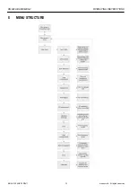
Page 12: ...VM242A BASICMES 2 OPERATING INSTRUCTIONS MU2H 1054GE25 R0411 12 Honeywell All rights reserved 8 MENU STRUCTURE ...

Page 13: ...OPERATING INSTRUCTIONS VM242A BASICMES 2 Honeywell All rights reserved 13 MU2H 1054GE25 R0411 9 HONEYWELL IN EMEA AND ASIA PACIFIC ...

Page 14: ...VM242A BASICMES 2 OPERATING INSTRUCTIONS MU2H 1054GE25 R0411 14 Honeywell All rights reserved 10 DATA SHEET ...

Page 15: ...s as well as some common valves of other manufacturers are stored in an internal database Manual input of the kv value is also possible Apart from differential pressure and flow measurement the BasicMes 2 has the following functions Two temperature sensor inputs for simultaneous using two sensors or successive using one sensor temperature measurements Data logging function with programmable interv...

Page 16: ...ate Normal 1Hz average value of four scans time slot four seconds Fast 4Hz no averaging Interface USB HP IR for communication with pocket printer Weight 2 5kg including accessories and carry case Dimensions 470 x 370 x 110mm length x width x height Pressure units mbar bar hPa kPa mH2O inH2O psi Temperature units C F Flow display up to 5mbar no display 0 1 000l h resolution 1l h 1 100m3 h resolutio...

Page 17: ...omputer Device only without accessories carry case or batteries VMS242A001 USB interface cable VMS242A005 Battery charger VMS242A006 Pressure hose Pressure hose assembly for all VM242 including bypass assembly red and blue pressure hose fittings and ballvalve VMS242A002 Spare filters set of two VMS242A003 SafeConTM plug for blue hose VMS242A008 SafeConTM plug with ball valve for red hose VMS242A00...

Page 18: ... Fax 49 6261 81393 www honeywell com EN0H 2323GE25 R0111 January 2011 2011 Honeywell International Inc Subject to change without notice Manufactured for and on behalf of the Environmental and Combustion Controls Division of Honeywell Technologies Sàrl Z A La Pièce 16 1180 Rolle Switzerland or its Authorized Representative ...

Reviews: