Programming and Operating Concepts
Video Recorder – User Manual
54
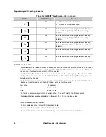
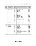
Table 3-4 Function Block Parameter Designators
(continued)
Function
Block
Type
Function Block
Name
Output
code
Parameter Name
Parameter
Type
SP Setpoint
Profiler
OV
A1
PV
SN
SH
SE
SA
SI
SR
E1
thru
E9
EA
EB
thru
EG
Output Value
Auxiliary Output Value
Process Variable (Guaranteed Soak PV #1)
Segment Number
Hold Status
End Status
Active Status
Active or Hold Status
Ready Status
Event#1 Output
thru
Event#9 Output
Event#10 Output
Event#11 Output
thru
Event#16 Output
Analog
Analog
Analog
Analog
Discrete
Discrete
Discrete
Discrete
Discrete
Discrete
$
Discrete
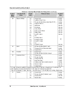
AL Alarm
PV
S2
OS
Process Variable (alarm’s input)
Compare Point (of Deviation alarm)
Output Status
Analog
Analog
Discrete
CN Constant
OV
PV
Output Value
Process Variable (Constant’s input)
Analog
Analog
CV Calculated
Value*
OV
PV**
A(n)
BC
S2
D(n)
OS
Output Value
Process Variable
Analog Output #n
Back Calculation
Auxiliary input (link to totalizer preset)
Discrete Output
Output Status
Analog
Analog
Analog
Analog
Analog
Discrete
Discrete
*CV output codes are available for programming only if the CV has been programmed. For example, you
cannot program an input parameter with CV1 OV unless CV1 has been programmed.
**Input to the following CV types: Peak Pick, 1 Point Block Avg., 1 Point Rolling Avg., Scaling, Signal Select
TL Totalizer
OV
PV
OS
S2
Output Value
Process Variable (Totalizer’s input)
Output Status
Preset Value
Analog
Analog
Discrete
Analog
Summary of Contents for VRX180
Page 1: ...Issue 3 03 03 US1I 6228 Video Recorder VRX180 User Manual ...
Page 2: ...Issue 3 03 03 US1I 6228 ...
Page 6: ...iv Video Recorder User Manual ...
Page 48: ...Installation Video Recorder User Manual 34 ...
Page 222: ...Setpoint Profiler Video Recorder User Manual 208 ...
Page 234: ...Online Operations Using Primary Displays Video Recorder User Manual 220 ...
Page 278: ...Appendix A Video Recorder User Manual 264 ...

