background image

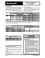
APPLICATION

The VS820 and VS821 are used on gas fired, standing

pilot appliances with 750 mV self-powered control systems.

The gas controls include a manual gas valve, safety shutoff,

single millivoltage automatic operator and pressure regula-

tor. Refer to Table 1 for capacity ratings and Table 2 for

pressure  regulators  and  temperature  ratings.  Separate

models are available for natural and LP gas; the controls

cannot be field converted.

Power  for  the  gas  control  and  the  control  system  is

provided  by  a  750  mV  Powerpile  generator.  We  recom-

mend the Q313 Thermopile Generator or the CS82, CS893,

CS894, or CS897 Pilot Burner Generators.

TABLE 1—VS820 AND VS821 PIPE SIZE AND CAPACITY RATINGS.

INLET x OUTLET

REDUCER FITTINGS

b

                   CAPACITY

a

 CAPACITY

MODEL

PIPE SIZE

cfh

m

3

/hr

SIZE

cfh

m

3

/hr

VS821

1/2 x 3/8

110

3.1

   —

  —

VS820

1/2 x 1/2

225

6.4

   —

  —

1/2 x 3/4

250

7.1

3/4 x 1/2

225

  6.4

1/2 x 3/8

110

  3.1

3/4 x 3/4

335

9.5

3/4 x 1/2

250

  7.1

3/4 x 1/2

225

  6.4

VS820

1 x 1

600

17.0

1 x 3/4

503

14.2

High Capacity

1 x 3/4

450

12.7

a

Capacity is based on 1000Btuh/ft

3

, 0.64 sp gr natural gas at 1 in. wc  pressure  drop [37.3 MH/m

3

, 0.64 sp gr natural gas

at  0.25 kPa pressure drop]. Use conversion factors in Table 3 to convert for other gases.

b

Reducer fittings must be obtained locally.

TABLE 2—PRESSURE REGULATOR AND TEMPERATURE RATINGS.

MODEL

PRESSURE

REGULATOR

TEMPERATURE RATING

TYPE

MODEL

°

F

°

C

VS820A,H

Standard

V5306A

32 to 175

0 to 79

VS821A

VS820C, VS821C

Step

V5307A

VS820D

Hi-Low

V5308A

VS820P

Step

V5307B

-40 to 175

-40 to 79

VS820V

Standard

V5306A

WARNING

FIRE OR EXPLOSION HAZARD

CAN CAUSE PROPERTY DAMAGE, SEVERE IN-

JURY, OR DEATH

Follow these warnings exactly:

1. Disconnect power supply before wiring to pre-

vent electrical shock or equipment damage.

2. To avoid dangerous accumulation of fuel gas,

turn off gas supply at appliance service valve

before starting installation and perform Gas

Leak Test following installation.

3. Do not bend pilot tubing at control or at pilot

after compression fitting has been tightened.

Gas  leakage  at  the  connection  fitting  may

result.

4. Always install sediment trap in gas supply line

to prevent contamination of gas control.

5. Do not force gas control knob. Use only your

hand to turn gas control knob. If the knob will

not  operate  by  hand,  the  control  should  be

replaced  by  a  qualified  service  technician.

Force or attempted repair may result in fire or

explosion.

INSTALLATION

WHEN INSTALLING THIS PRODUCT…

1. Read  these  instructions  carefully.  Failure  to  follow

them  could  damage  the  product  or  cause  a  hazardous

condition.

2. Check the ratings given in these instructions and on

the product to make sure the product is suitable for your

application.

3. Make sure installer is a trained, experienced service

technician.

4. After completing installation, use these instructions to

check product operation.

TABLE 3—GAS CAPACITY CONVERSION FACTORS.

SPECIFIC

MULTIPLY

TYPE OF GAS GRAVITY

LISTED CAPACITY BY

Manufactured      0.60                   0.516

Mixed                  0.70                   0.765

Propane              1.53                   1.62

D.T.

      Form Number 95-6994—8

Rev. 4-89

            ©Honeywell Inc. 1989

VS820A,C,D,H,P,V AND VS821A,C

MILLIVOLTAGE COMBINATION

GAS CONTROLS

Summary of Contents for VS820A

Page 1: ...D Hi Low V5308A VS820P Step V5307B 40 to 175 40 to 79 VS820V Standard V5306A WARNING FIRE OR EXPLOSION HAZARD CAN CAUSE PROPERTY DAMAGE SEVERE IN JURY OR DEATH Follow these warnings exactly 1 Disconnect power supply before wiring to pre vent electrical shock or equipment damage 2 To avoid dangerous accumulation of fuel gas turn off gas supply at appliance service valve before starting installation...

Page 2: ...able or 50 ft 15 3 m of 2 wire 16 gauge cable INLET AND OUTLET ADAPTERS If adapters are needed prepare control as follows 1 Remove seal over control inlet or outlet 2 Apply moderate amount of good quality pipe com pound to adapter leaving two end threads bare Refer to Fig 1 On LP installation use compound resistant to LP gas Do NOT use Teflon tape 3 Insert adapter in control and thread carefully u...

Page 3: ... Figs 3 and 4 If tubing is used connect tubing to coupling CONNECT PILOT GAS TUBING 1 Cut tubing to desired length and bend as necessary for routing to pilot burner Do not make sharp bends or deform tubing Do not bend tubing at control after compres sion nut has been tightened as this may result in gas leakage at the connection 2 Square off and remove burrs from end of tubing 3 Unscrew brass compr...

Page 4: ...out turn gas control knob clockwise to OFF Repeat steps 1 3 4 Release gas control knob If pilot remains lit turn counterclockwise to ON ADJUST PILOT FLAME Thepilotflameshouldenvelop3 8to1 2in 10to13mm of the tip of the generator Refer to Fig 9 Fig 9 Proper flame adjustment TURN ON MAIN BURNER Follow instructions provided by appliance manufacturer or turn up thermostat to call for heat CHECK AND AD...

Page 5: ...eld adjustable The HI or LOW flame setting is selected by position ing the white knob on the regulator Refer to Fig 10 Fig 10 HI and LOW settings for VS820D 1 Check the LOW flame setting listed on the appliance nameplate Gas control LOW flame setting should match this rating 2 With main burner operating check gas control outlet flowrateusingthemeterclockingmethodoroutletpressure using a manometer ...

Page 6: ...ge 4 b Compression fitting has a gas leak replace old compression fitting or tighten new one Refer to page 3 c Pilot burner tubing or orifice is clogged replace combination gas control Refer to page 1 IF PILOT GOES OUT WHEN GAS CONTROL KNOB IS RELEASED 1 Make sure the gas control knob is held in at least one minute to allow the generator time to heat 2 Check pilot flame adjustment refer to page 4 ...

Page 7: ...ontrol knob all the way and hold in Immedi ately light the pilot with a match Continue to hold the control knob in for about one 1 minute after the pilot is lit Release knob and it will pop back up Pilot should remain lit If it goes out repeat steps 5 10 10 Replace pilot access panel 11 Turn gas control knob counterclockwise to ON 12 Replace control access panel 13 Turn on all electric power to th...

Page 8: ......

Reviews: