background image

PRODUCT DATA

Put Bar Code Here

95C-10883-03

VU443A; VU444A; VU843A; VU844A 

Fan Coil Valve Actuators

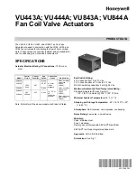
The VU443, VU444, VU843, and VU844 Fan Coil Valve 

Actuators are used in conjunction with the VU52, VU53, and 

VU54 fan coil valves for controlling the flow of hot or chilled 

water. These valves are humidity resistant and are suitable for 

use in condensing, non-corrosive environments.

SPECIFICATIONS

Actuator Electrical Rating & Connections: 

10 VA maxi-

mum.

Note: Motors for all the above models are Class A, Plated.

End Switch Rating:

2.2 A inductive from 5 to 110 Vac.

1.0 A inductive above 110 Vac to 277 Vac.

Min. DC switching capability: 5 mA @ 24 Vdc.

Maximum Ambient @ Fluid Temperature Rating:

Standard models (with class A motor):

125° F (52° C) ambient @ 200° F (93° C) fluid.

Minimum Ambient Temperature: 

34° F (1° C).

Shipping and Storage Temperature: 

-40° F to 150° F (-40° 

C to 65° C).

Atmosphere: 

Non-corrosive, non-explosive, condensing.

Noise Rating: 

Low noise - non-obtrusive.

Materials:

Case: stainless steel.

Cover: aluminum.

Sector gear: reinforced with KEVLAR

®

 brand fiber.

KEVLAR

®

 is a Dupont registered trademark.

Approvals: 

CSA C/US Certified.

Dimensions: 

See Fig. 1.

Model

Control 

CIrcuit

Current 

Draw (A)

End 

Switch

Connection

/Leads

Application

VU443A

120V, 

60Hz

0.07

None

6” motor 

leads 

standard.

18”, 36”, or 

96” 

Leadwires 

optional.

2-way, normally 

open (use 

VU444, 

VU844);

VU443E

SPST

VU444A

None

2-way, normally 

closed (use 

VU443, 

VU843);

VU843A

VU844A

24V, 

50-60Hz

0.32

None

3-way, diverting 

(use VU444, 

VU844).

Summary of Contents for VU443A

Page 1: ...ty 5 mA 24 Vdc Maximum Ambient Fluid Temperature Rating Standard models with class A motor 125 F 52 C ambient 200 F 93 C fluid Minimum Ambient Temperature 34 F 1 C Shipping and Storage Temperature 40 F to 150 F 40 C to 65 C Atmosphere Non corrosive non explosive condensing Noise Rating Low noise non obtrusive Materials Case stainless steel Cover aluminum Sector gear reinforced with KEVLAR brand fi...

Page 2: ...tuator attach ment easier 2 Install valve body into pipe 3 Wiring connections may be made either before or after the actuator is installed on the valve body 4 Place manual operating lever on the actuator in the MAN OPEN position 5 Line up motor coupling to slot in shaft of body and fit the head onto the valve body ensuring that the shaft seats correctly See Fig 2 6 Snap actuator onto body by press...

Page 3: ...own through slot in the wiring hole so that the strain relief nut is inside the actuator hous ing 6 Secure nut onto strain relief 7 Install actuator cover Fig 4 Typical wiring for VU40 series actuator Fig 5 T822 Thermostat VU80 series actuator hookup OPERATION CAUTION On 24V systems never jumper the valve coil terminals even temporarily This can burn out the heat anticipator in the thermostat AUTO...

Page 4: ...below the room temperature 4 Observe the control devices The valve should close and the auxiliary equipment should stop SET TO COOLING MODE 1 Lower the setpoint on the zone thermostat below the room temperature to initiate a call for cooling 2 Observe all control devices the valve should open 3 Raise the setpoint on the zone thermostat above the room temperature 4 Observe the control devices The v...

Reviews: