background image

PRODUCT DATA

68-0258ES-1

W8835A EnviraZone Panel

APPLICATION

The W8835A EnviraZone Panel controls single-stage, multi-

stage, conventional or heat pump heat/cool equipment. It 

controls three zones, and is expandable up to nine zones with 

two additional W8703A Damper Interface Modules (DIM).

For Internet access: http://yourhome.honeywell.com.

For technical support, call: 1-800-828-8367.

American Lung Association® Health House® 

Program and Honeywell Working Together 

For Better Air

Did you know that the average person breathes 3400 

gallons(12,870 liters) of air each day * and spends 90% of that 

day inside?**

Indoor air quality products from Honeywell are designed to 

help make your home more comfortable—from zoning 

products that allow you to control the temperature in individual 

areas of the home to humidifiers and comfort control centers 

that help balance the moisture content of your indoor air.

Honeywell is proud to be a partner of the American Lung 

Association® Health House® program that provides 

guidelines for constructing homes with improved air quality 

and ventilation. 

For more information on ways to improve the air inside your 

home, please visit the Health House website at: 

www.healthhouse.org 

and the American Lung Association website at: 

www.lungusa.org

The American Lung Association and its Health House 

program do not endorse products.

For more information about Honeywell Indoor Air Quality 

products, visit: http://yourhome.honeywell.com or 

call: 1-800-345-6770 x531.

*EPA.National Air Quality 1999 Status & Trends.

**

Indoor Air Pollution, An Introduction for Health Professionals

, EPA, US 

Government Printing Office #1994-523-217/81322.

IMPORTANT

Please read these instructions and keep them in your 

records.

Contents

Application.........................................................................1

Features ............................................................................2

Specifications ....................................................................2

Ordering Information .........................................................2

Installation .........................................................................4

Startup and Checkout........................................................8

Operation...........................................................................8

Troubleshooting.................................................................11

Summary of Contents for W8835A

Page 1: ... centers that help balance the moisture content of your indoor air Honeywell is proud to be a partner of the American Lung Association Health House program that provides guidelines for constructing homes with improved air quality and ventilation For more information on ways to improve the air inside your home please visit the Health House website at www healthhouse org and the American Lung Associ...

Page 2: ...ailure indication SPECIFICATIONS Input Ratings Voltage 20 30 Vac 50 60 Hz Power 11 VA nominal Output Ratings 1 5A run 200 000 cycles 30 Vac 3 5A inrush 1 5A run 100 000 cycles 30 Vac 7 5A inrush Humidity Ratings 90 percent RH at 95 F non condensing Temperature Ratings Shipping 20 to 120 F Operating 40 to 150 F LED SYSTEM mode LEDs 5 used to communicate equipment status Red Heat Heat mode Green Coo...

Page 3: ...more than ten dampers when using two 40 VA transformers Use SDCR for additional dampers required Fig 1 W8835 dimensions in in mm Motor Terminal Damper Action Common M1 Common Open M4 Power Open Closed M6 Power Close Table 1 Recommended Dampers Honeywell Damper Type Round Rectangular Power open power closed for systems 2000 cfm MARD D640 D642 using ML6161 Motor Actuator Spring open power closed for...

Page 4: ...only Fig 2 W8835 mounting location Wiring CAUTION Voltage Hazard Can cause electrical shock or equipment damage Disconnect power before continuing installation Wiring must comply with applicable codes ordinances and regulations Table 2 Required Accessories Not Supplied with Panel Accessory Description Bypass Rating cfm 40 VA transformers AT140A1042 Capacity protector C7835A1009 Round static pressu...

Page 5: ... T2 T1 C R This diagram shows the typical equipment thermostat and damper motor connections For specific wiring refer to the Installation Instructions C R 24 VAC 40 VA Optional Transformer required if system load is greater than single transformer output C R 24 VAC 40 VA Panel Transformer Damper XFRM Enviracom XFRM HEAT COOL PURGE FAN EM HT COMM ZONE 1 ZONE 2 ZONE 3 HVAC Equipment L C Rh Rc W1 E H...

Page 6: ...factory installed Y1 Y2 G O B Heating Transformer HP Fault Common HP Fault 24 VAC Equipment Cooling Transformer Compressor Reversing Valve Cooling Heating Fan Relay C L Auxiliary Heat 1 1 FIELD INSTALLED JUMPER M20599 HVAC Equipment RH RC C L W1 E W2 W3 AUX Single Transformer Heating Cooling systems require a jumper to be installed connecting RH and RC factory installed Y1 Y2 G O B Heating Transfo...

Page 7: ...Damper or ML6161 Actuator to panel Fig 12 MARD or ML6161 Damper Motor Actuator using R8222 Relay wiring Transformer Wire the transformers to the panel see Fig 13 One 40 VA 24 Vac transformer is required to operate the panel and up to five ARD or ZD dampers The transformer is connected to terminals R and C The auxiliary transformer is required if up to ten dampers are connected to the panel If more...

Page 8: ... setpoint to call for heat a Verify that the heat LED is red NOTE The furnace heat may not come on immedi ately Allow at least 5 minutes for heat to begin after the thermostat calls for heat b Verify that Zone one LED remains green c Verify that all other zone LEDs are not illuminated d Change thermostat mode from Heat to Off 9 Set Zone two thermostat to heat and raise the setpoint to call for hea...

Page 9: ...n mode ceases and the heat or cool call is honored When the zone calling is satisfied and Purge mode has ended the circulation call resumes Single and Multi Stage Conventional Heat Operation The panel can control up to three stages of heating and two stages of cooling based on thermostat demand Set DIP switches 1 and 2 for 1 2 or 3 stages of heat Set DIP switch 7 for one or two stages of cooling H...

Page 10: ...e of Greatest Demand Discovery Discovery is an automatic system configuration program where the panel configures itself to operate with controls connected to the EnviraCom bus The panel enters Discovery when the Discovery button on the panel is pressed Rebooting Microprocessor To reset the microprocessor press and release the Boot button The system reboots and enters the Purge mode EnviraCom Furna...

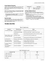
Page 11: ...orrespond to the zones being controlled See W8703 Installation Instructions Wire terminals 1 2 and 3 from the additional thermostats to terminals 1 2 and 3 on any of the panels TROUBLESHOOTING DIP Switch 8 Fan Control Off Fan on in heat by panel On HVAC control of fan Table 4 Troubleshooting Symptom Possible Cause Action No LEDs are Illuminated No power to the board Check for 24 Vac 10 across R an...

Page 12: ...tion On Up Default Off Down 3 Type of furnace Conventional non communicating EnviraCom Communicating 4 Purge time Two minutes 3 5 minutes 5 Fan control during purge HVAC controlled Panel controlled 6 Damper control during purge Last zone s calling open during purge Open all dampers during purge 7 Heat pump compressor stages One stage Two stages 8 Fan control in heat Fan controlled by panel in cool...

Page 13: ...erior Honeywell se enorgullece de asocia rse con el programa American Lung Association Health House que proporciona lineamientos para construir hogares con ventilación y un aire de mejor calidad Si desea más información sobre las maneras de mejorar la calidad de aire en el interior de su hogar por favor visite el sitio Web de la Health House en www healthhouse org y el sitio Web de la American Lun...

Page 14: ...ACIONES Valores nominales de entrada Voltaje 20 30 Vca 50 60 Hz Potencia 11 VA nominales Valores nominales de salida 1 5 A de operación 200 000 ciclos 30 Vca 3 5 A de entrada 1 5 A de operación 100 000 ciclos 30 Vca 7 5 A de entrada Clasificaciones de humedad 90 por ciento de humedad relativa a 95 F 31 5 C no condensante Clasificaciones de temperatura Envío 20 a 120 F 26 a 44 C Operación 40 a 150 ...

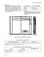
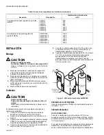
Page 15: ...para marcación interna y externa y el módulo de interfaz del amortiguador W8703 para controlar zonas adicionales Figura 1 Dimensiones del W8835 en mm pulgadas Terminal del motor Acción amortiguadora Común M1 Común Abierto M4 Abre eléctricamente Cerrado M6 Cierra eléctricamente Tabla 1 Amortiguadores recomendados Tipo de amortiguador Honeywell Redondo Rectangular Abierto cerrado eléctricamente para...

Page 16: ...Conecte un transformador de 40 VA y 24 voltios a las conexiones R vivo y C Común Este debe ser un transformador dedicado Vea la Figura 3 6 Conecte el transformador auxiliar de 40 VA 24 voltios a T1 y T2 si se requiere potencial adicional para los amortiguadores No se requiere este segundo transformador sin embargo el consumo total de potencia del panel y del amortiguador está limitado a 40 VA si n...

Page 17: ...o Vea las Figuras 5 y 6 Vea las Figuras 7 y 8 en cuanto al equipo de la bomba de calefacción de dos etapas Cablee la válvula de inversión al terminal del equipo O B El interruptor 9 DIP configura este terminal para operar como un terminal de cambio de O enfriamiento o B calefacción Si el equipo de la bomba térmica tiene un terminal L que se enciende al fallar la bomba térmica conéctelo al terminal...

Page 18: ...NA 1 M6M4M1 ZONA 2 AMORTIGUADORES BUS ENVIRACOM M6M4M1 ZONA 3 1 2 3 1 2 3 1 2 3 1 2 3 1 2 3 se puede conectar a cualquier conjunto de 1 2 3 terminales 1 2 3 1 2 3 1 2 3 Puentes XFRM Conecte los puentes instalados de fábrica en posición abierta si usa un solo transformador ZONE DAMPER MOTORS M1 common M4 power open M6 power closed M20596 PURGE OVERRIDE BOOT DISCOVERY T2 T1 C R This diagram shows th...

Page 19: ...2 W3 AUX Los sistemas de calefacción enfriamiento de un solo transformador requieren que se instale un puente que conecte a RH y RC instalado en fábrica Y1 Y2 G O B Transformador calefacción Falla del común de HP Falla de HP Equipo de 24 VCA Transformador enfriamiento Relé calef de emergencia Compresor Válvula de inversión enfr calef Relé del ventilador C L Calefacción auxiliar 1 1 PUENTE INSTALAD...

Page 20: ... se conectan hasta diez amortiguadores al panel Si se requieren más de cinco amortiguadores para una zona o si se requieren más de diez amortiguadores para el W8835 use el relé de control de amortiguador esclavo SDCR El transformador auxiliar se cablea a los terminales T1 y T2 Si un transformador da energía al panel encuentre los puentes XFRm rotulados E2 y E3 Coloque el puente a través de cada co...

Page 21: ...para detener la señal de calefacción a esa zona Verifique que el LED de la zona uno se apague y que el LED de la zona dos cambie a verde 9 Repita para la zona tres 10 Como alternativa baje el punto de referencia para enviar la señal de enfriamiento Verifique que el LED verde de enfriamiento se ilumine OPERACIÓN Secuencia de operación Cuando no se envíe una señal de calefacción enfriamiento o venti...

Page 22: ... una señal de calefacción o enfriamiento en este período de tiempo se suspende el modo de circulación y se respeta la señal de calefacción o enfriamiento Cuando la zona que envía la señal está satisfecha y ha terminado el modo de purga se reanuda la señal de circulación Operación de calefacción convencional de una y múltiples etapas El panel puede controlar hasta tres etapas de calefacción y dos e...

Page 23: ...l de otras zonas puesto que la zona que requiere el mayor acondicionamiento energiza al equipo y las demás zonas se cierran según quedan satisfechas Asimismo se abren más amortiguadores al mismo tiempo con más frecuencia ante las señales del equipo lo cual resulta en menos uso de amortiguación de derivación y en un uso más eficiente del equipo Todas las zonas quedan satisfechas sin embargo si en c...

Page 24: ... reinicie Para eliminar el corto compruebe el cableado de los amortiguadores y del transformador Ventilador encendido en la calefacción El ventilador del sistema se puede configurar para que se encienda con una señal de calefacción según lo requieran los sistemas hidráulicos de aire o de calefacción eléctrica Configure la función del ventilador utilizando el interruptor 8 DIP Cuando se configure p...

Reviews: