4
W884B,E
INSTALLATION
Installation
WHEN INSTALLING THIS PRODUCT…
1. Read these instructions carefully. Failure to fol-
low them could damage the product or cause a hazard-
ous condition.
2. Check the ratings given in the instructions and on
the product to make sure the product is suitable for your
application.
3. Installer must be a trained, experienced service
technician.
4. After installation is complete, check out product
operation as provided in these instructions.
CAUTION
1. Disconnect power supply before beginning
installation to prevent electrical shock or
equipment damage.
2. On gas systems, turn off gas before starting
installation.
LOCATION
Locate the W884 about 5 ft [1.5 m] above the floor in
an area with good air circulation at average temperature.
Do not mount the W884 where it may be affected by:
— drafts, or dead spots behind doors and in corners.
— hot or cold air from ducts.
— radiant heat from the sun or appliances.
— concealed pipes and chimneys.
— unheated (uncooled) areas such as an outside wall
behind the thermostat.
MOUNTING
IMPORTANT: The thermostat used with the W884 was
mounted at true level when calibrated at the fac-
tory. The W884 must be level to maintain calibra-
tion.
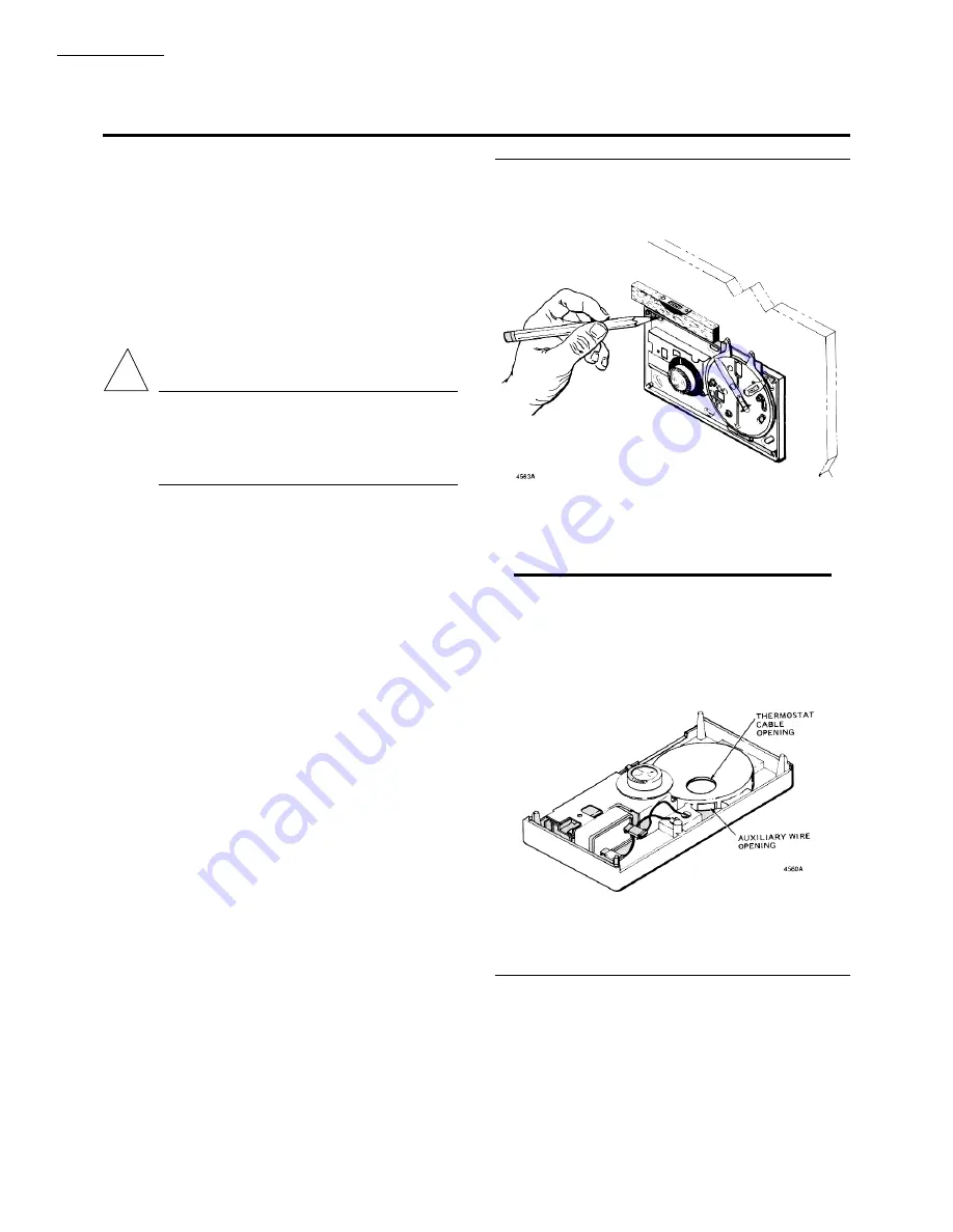
1. Remove cover and thermostat and level W884 at
the selected location. Mark locations for mounting screws
and wiring access hole. See Fig. 2.
2. Drill a 1/2 to 3/4 in. [13 to 19 mm] hole for the
wires, and small pilot holes for the mounting screws.
3. Run cable and auxiliary wires (if used) to location.
Pull in the required number of wires. All wiring is 24V.
4. Carefully slip the thermostat wires through the
hole in the subbase, and insert humidistat and auxiliary
wires (if used) through the square wiring hole on the side
of the subbase platform. See Figs. 3 and 4.
Fig. 2—Level the W884 and then mark the
position of mounting holes with a pencil.
!
Fig. 3—Thermostat wires are brought through
the hole on the subbase; wires for the humi-
distat are brought through the hole on the side
of the subbase platform.


