5
60-2289—6
W884B,E
INSTALLATION
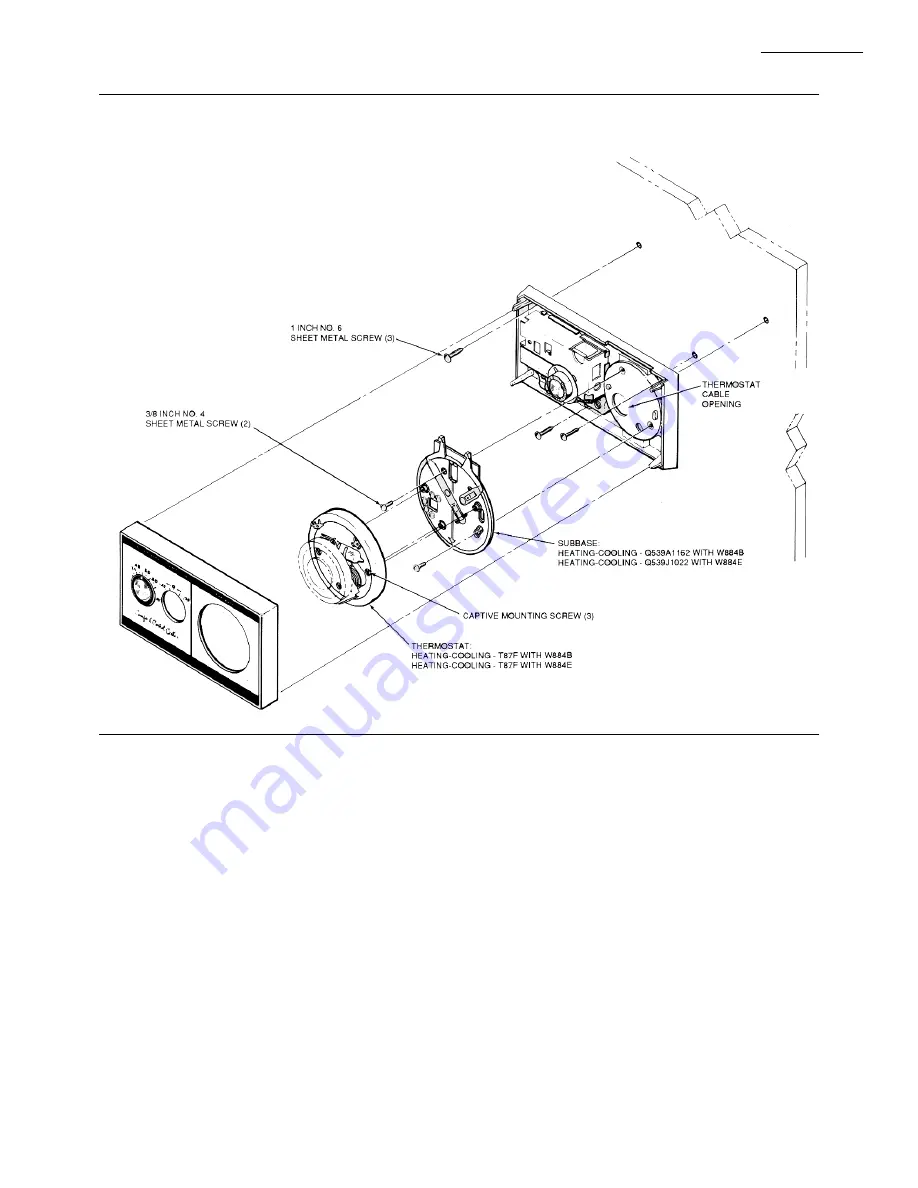
5. Use the three 1-in. screws to mount the W884 on
the wall. Before tightening the screws, level as accu-
rately as possible using a spirit level placed on top of the
W884. Tighten the screws. For mounting on a junction
box, use part no. 133262A Backplate Assembly (order
separately).
6. Connect the color-coded wires to the subbase and
humidistat (see Wiring section). Push excess wire back
into wall, and plug the hole to prevent drafts from affect-
ing the W884.
7. Mount the thermostat, and replace W884 cover.
WIRING
Disconnect power supply to prevent electrical shock
or equipment damage.
All wiring must comply with local codes and ordi-
nances.
Wiring to the W884 must be NEC Class 2.
Humidistat requires separate 24V power supply.
Refer to the wiring diagrams and instructions packed
with the thermostat and subbase, and Figs. 5-9.
Fig. 4—The W884 comfort control center has interchangeable thermostats and subbases to provide for
several types of operation.


