WEB/CP-202-XPR AND WEB/CP-602-XPR CONTROLLERS
13
95-7775—01
4.
Carefully insert the pins of the option card into the socket headers of the option card slot.
The mounting holes on the option board should line up with the standoffs on the base board. If they do not, the connector is
not properly aligned. Press until the option card is completely seated.
5.
Place the custom end plate that came with the option card over the connector(s) of the option card.
6.
With the mounting holes aligned with the standoffs, place the two screws through the end plate, and into the standoffs on
the controller’s base board. Using a screwdriver, hand tighten these screws.
7.
Replace both covers on the controller.
About Remote I/O Modules
The WEB/CP-202-XPR and WEB/CP-602-XPR have an integral 6-pin connector to support remote I/O modules. The connector
provides both 15 Vdc power and RS-485 communications to modules on that connected trunk, and is located below the 6-
position Digital Output (DO) I/O connector (see Fig. 6. on page 11).
Each remote I/O module has a DIN-mount base, and provides two (2) 6-pin connectors that allow you to “chain” multiple modules
together into one assembly. Table 2 lists the currently available modules.
NOTE: The
maximum
number of IO-16-REM-H modules supported varies by platform, as follows:
•
3 maximum
IO-16-REM-H modules if a WEB/CP-202-XPR.
•
15 maximum
IO-16-REM-H modules if a WEB/CP-602-XPR.
NOTE: Note that the actual maximum number of supported IO-16-REM-H modules
may be less
, as resource usage varies with
each application database
WIRING SUMMARY
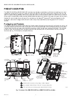
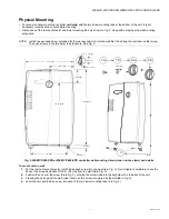
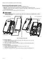
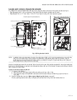
See Fig. 6. on page 11 to locate connectors and other components on the controller.
Make connections to the controller in the following order:
1.
Install any option board (LON, RS-485, RS-232) in the available option slot. See
Installing an Option Card
on page 12 for
general procedures. For complete details, refer to the specific documentation that accompanied the option.
2.
If applicable, insert the SIM card for the unit’s GPRS modem, and attach the GPRS antenna if not already attached (see
Inserting a SIM card and attaching GPRS antenna
on page 10).
3.
After mounting, wire earth ground and 24V power (circuit de-energized). See
Earth Ground and 24V Input Power
on
page 14.
4.
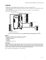
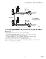
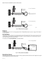
Wire I/O points to the controller’s I/O terminals and earth ground terminal strip (for cable shield wires). See
I/O Wiring
on
page 15 for more details.
5.
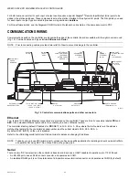
Connect communications cables. See
Communications Wiring
on page 20 for ports available on the controller base unit.
For ports on any installed option board (LON, RS-485, RS-232, modem) see the specific mounting and wiring guide for any
additional details.
6.
Apply power to the unit. See
Power Up and Initial Checkout
on page 23.
Table 2. Remote I/O modules compatible with the WEB/CP-202-XPR AND WEB/CP-602-XPR.
Model
Description
Notes
IO-16-REM-H
Remote I/O RS-485 Module
DIN-mountable RS-485 comm module that provides
16 points I/O, with I/O point types as noted.
Provides the following I/O points:
•
8 - Universal Inputs (UIs).
•
4 - Digital Outputs (DOs), SPST-relay type.
•
4 - Analog Outputs, 0–10Vdc type.
Wiring is covered in a separate document, see the
IO-16-REM-H Installation and Configuration
Instruction
s.


