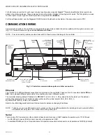
WEB/CP-202-XPR AND WEB/CP-602-XPR CONTROLLERS
23
95-7775—01
WIRING TO REMOTE I/O MODULES
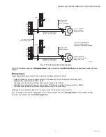
Wiring to remote I/O modules (IO-16-REM-H) typically provides both 15 Vdc power and 12V battery backup to the modules,
along with RS-485 communications. See Fig. 17.
Fig. 17. RS-485 cabling between WEB/CP-202-XPR and WEB/CP-602-XPR and remote I/O modules.
For related information, see the
IO-16-REM-H Installation and Configuration Instructions
document.
POWER UP AND INITIAL CHECKOUT
Following all mounting and wiring (I/O Wiring, Communications Wiring, External 12V Backup Battery, Wiring to Remote I/O
Modules), perform the following:
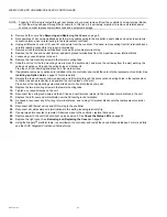
Initial power up and checkout
1.
Apply Power.
2.
Check the Status LEDs.
Also see the section
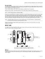
About the Backup Batteries
on page 24.
PS
–
PS
+
BB
RS-485
–
RS-485
+
485 GND
PS
–
PS
+
BB
PS
–
PS
+
BB
PS
–
PS
+
BB
– +
S
– +
S
– +
S
POWER SUPPLY (15V) AND 12V BACKUP BATTERY IS
WIRED TO REMOTE IO MODULES USING A 3-CONDUCTOR
WITH SHIELD CABLE.
USE THE SHORTEST WIRING ROUTE POSSIBLE FOR
POWER WIRING. STAR, TEE, BUS AND LOOP
TOPOLOGIES ARE ALL PERMISSIBLE.
USE STANDARD VOLTAGE DROP CALCULATIONS FOR DISTANCE
AND WIRE GAGE TO ENSURE THAT VOLTAGE AT THE FURTHEST
REMOTE MODULE IS NO LESS THAN 11.5 VDC.
FOR LONGER RUNS, AN AUXILIARY POWER SOURCE MAY BE
REQUIRED FOR THE REMOTE MODULES.
CONNECT SHIELD WIRE TO
GROUND AT ONE END ONLY.
RS-485 COMMUNICATIONS IS DAISY-CHAINED TO
REMOTE IO MODULES USING A SHIELDED TWISTED-PAIR CABLE.
CONNECT RS-485 SHIELD WIRE TO
GROUND AT ONE END ONLY.
NOTE:
A MAXIMUM OF THREE REMOTE IO-16-REM-H
MODULES IS RECOMMENDED FOR THE
WEB/CP-202-XPR, DUE TO PLATFORM RESOURCE
CONSIDERATIONS.
IO-16-REM-H IO-16-REM-H
WEB/CP-202-XPR, WEB/CP-602-XPR
M28880

